5.3.9 Example: Using the Profile Position Mode
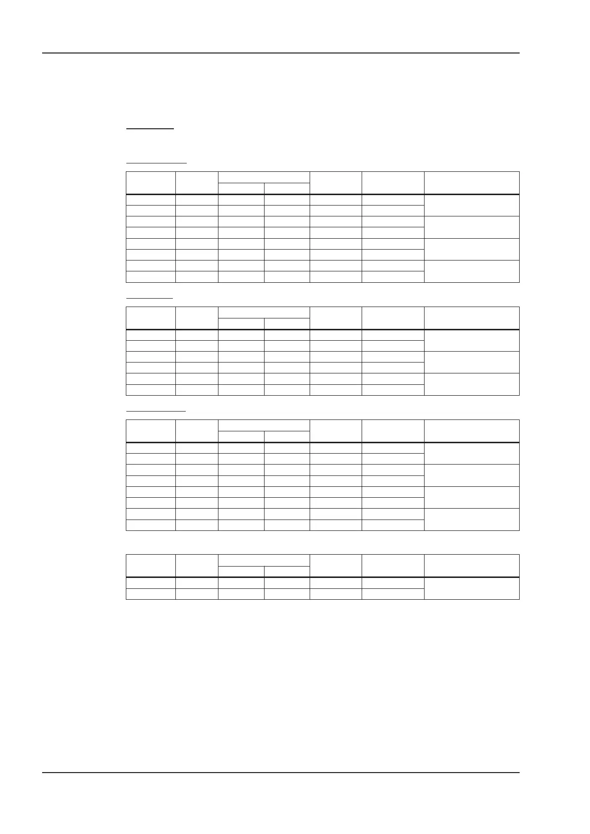
This example shows the operation of the Profile position mode. For this, the PDOs are set as fol
-
lows:
First RPDO
No special mapping necessary, because the default mapping enters the controlword RXPDO1.
Second RPDO
COB-ID
Control
byte
Index
Sub-
index
Data Comment
Low byte High byte
603 2F 01 16 00
h
00 00 00 00
RPDO2: delete mapping
583 60 01 16 00
h
00 00 00 00
603 23 01 16 01
h
20 00 7A 60
RPDO2, entry 1:
target_position
583 60 01 16 01
h
00 00 00 00
603 23 01 16 02
h
20 00 81 60
RPDO2, entry 2:
profile_velocity
583 60 01 16 02
h
00 00 00 00
603 2F 01 16 00
h
02 00 00 00
enter number of mapped
objects
583 60 01 16 00
h
00 00 00 00
First TPDO
COB-ID
Control
byte
Index
Sub-
index
Data Comment
Low byte High byte
603 2F 00 1A 00
h
00 00 00 00
TPDO1: delete mapping
583 60 00 1A 00
h
00 00 00 00
603 23 00 1A 01
h
10 00 41 60
TPDO1, entry 1:
profile statusword
583 60 00 1A 01
h
00 00 00 00
603 2F 00 1A 00
h
01 00 00 00
enter number of mapped
objects
583 60 00 1A 00
h
00 00 00 00
Second TPDO
COB-ID
Control
byte
Index
Sub-
index
Data Comment
Low byte High byte
603 2F 01 1A 00
h
00 00 00 00
TPDO2: delete mapping
583 60 01 1A 00
h
00 00 00 00
603 23 01 1A 01
h
20 00 64 60
TPDO2, entry 1:
position_actual_value
583 60 01 1A 01
h
00 00 00 00
603 23 01 1A 02
h
20 00 6C 60
TPDO2, entry 2:
velocity_actual_value
583 60 01 1A 02
h
00 00 00 00
603 2F 01 1A 00
h
02 00 00 00
enter number of mapped
objects
583 60 01 1A 00
h
00 00 00 00
The second TPDO should be sent with every SYNC by the servoamplifier.
COB-ID
Control
byte
Index
Sub-
index
Data Comment
Low byte High byte
603 2F 01 18 02
h
01 00 00 00
TPDO2 with every SYNC
583 60 01 18 02
h
00 00 00 00
122 CANopen for S300/S700
Appendix 11/2018 Kollmorgen

 Loading...


