204 General Maintenance
6. Loosen both bolts (see Figure 3-298) and adjust the proximity switch so that it gets triggered (its
amber light turning on).
Triggering occurs when the plate (target) is detected by the switch.
7. Retighten the bolts.
8. Engage the hydraulic pump and check for proper operation.
Make sure that the proximity switch detects the plate properly.
Ideally, there should be a gap of approximately 3/16 inch between the proximity switch and the plate.
If this is not the case, apply the following procedure:
To adjust the gap between the proximity switch and the plate:
1. On the proximity switch, loosen the nuts located on each side of the proximity switch bracket
(see Figure 3-298).
2. Push or pull the proximity switch until there is a gap of 3/16 inch between the plate and the
switch.
3. Tighten up both nuts.
4. Make sure that the proximity switch detects the plate properly.
5. Test the packer for a full cycle.
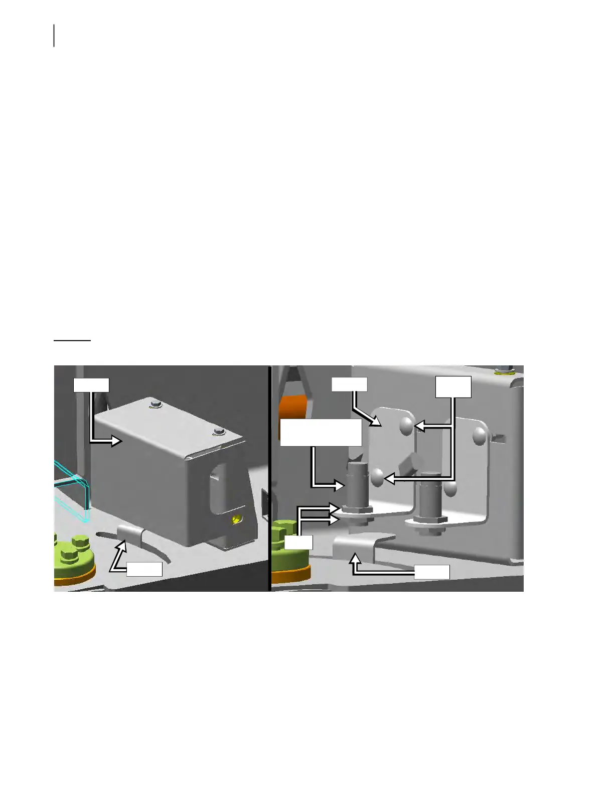
Figure 3-298
Proximity switch assembly
Bracket
Plate
Bolts
Nuts
Cover
Plate
Extend proximity
switch