Hydraulic System 299
3. Stop the engine.
4. Set the relief cartridge on the regeneration valve to maximum adjustment by screwing the
adjustment screw clockwise.
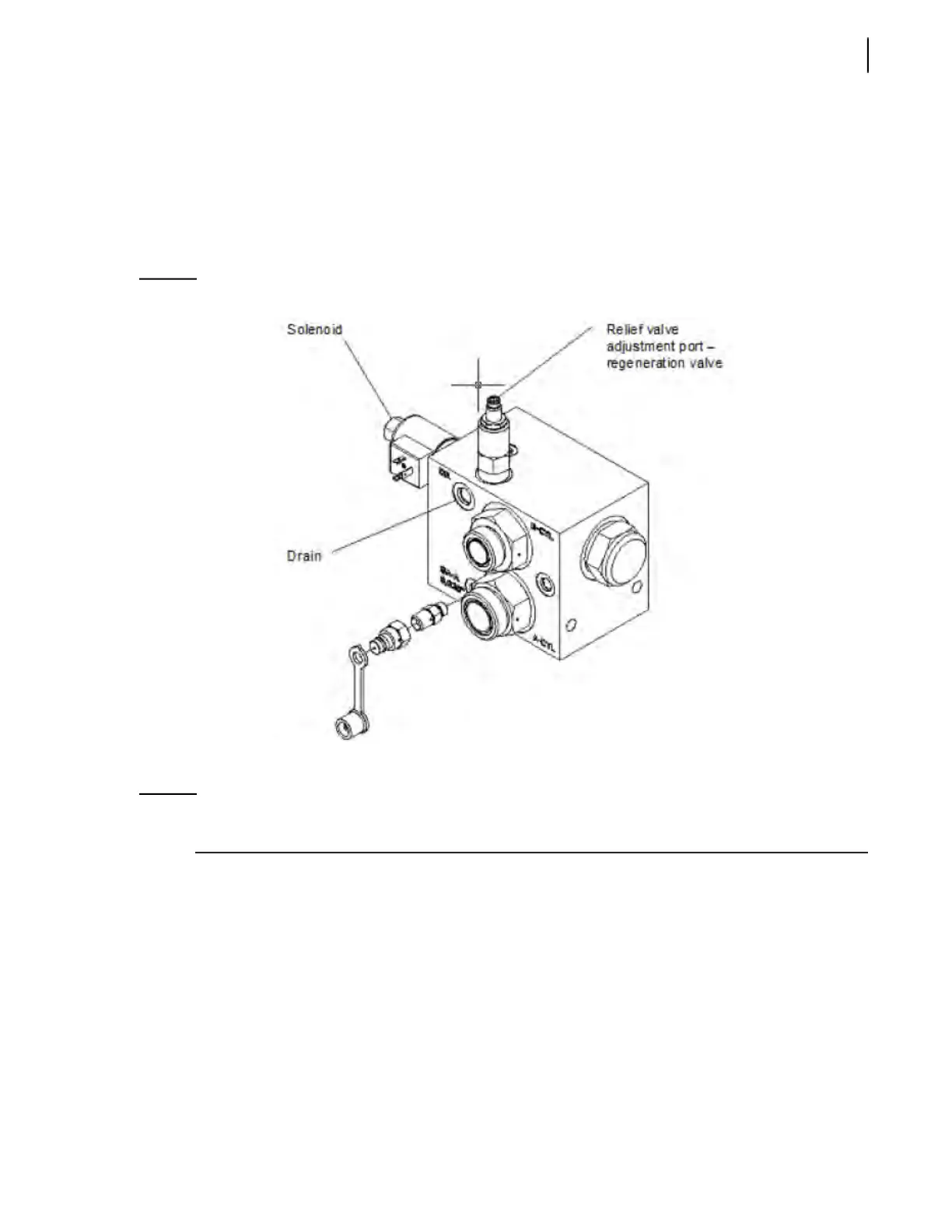
5. Disconnect the drain line from the regeneration valve (see Figure 5-44) and put it in a container
in order to see the flow that comes from said valve and place a plug (male or female as
appropriate) at the end of the disconnected line to prevent oil from flowing when the truck is
running.
Figure 5-44
Regeneration valve
6. Start the truck and let it idle.
NOTE: Steps 7-10 are to be followed only in case of a first installation. Please ignore these steps when
proceeding with subsequent pressure adjustments.
7. Loosen the nut that secures the solenoid to the regeneration valve.
8. If the regeneration valve block carries the following number, HYV08200 or HYV08200-01, the
solenoid must move freely (non actuated/non magnetized). If the block has the number
HYV08210 or HYV08210-01 on it, the solenoid must not move (actuated/magnetized).
9. If step 8 is not followed, the electrical logic is wrong and must be changed. If step 8 is followed, go
to step 10.
10. Retighten the nut that secures the solenoid to the regeneration valve.
11. Press the green push-button on the packer control station to move the packer forward until it is
fully extended.