346 Troubleshooting
Step #3)
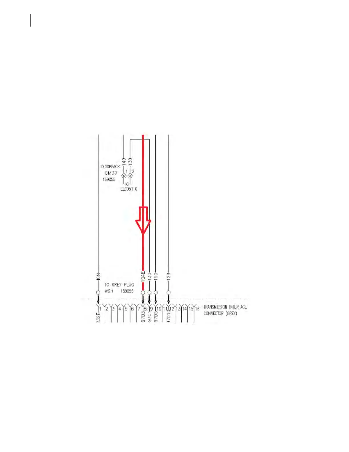
A) Locate output “OUT 12” and force it “ON”. With this output forced move to the appropriate
Labrie/chassis interface connector (see body serial number specific drawings for exact connector
number). Measure voltage on the pump trans request wire (104E). If voltage is present proceed to
step #4.
B) If no voltage is present, verify that voltage is leaving Node 10, wire 104o, pin 02, connector X20.
If voltage is not leaving the module then the node 10 is defective/damaged; replace it. If voltage is
leaving the module; there is one of two issues. Either a break in the wiring caused by an Emergency
stop switch/panic bar or an outside fault (such as an abraded/cut wire, corrosion/water in a
connector, etc.) is present. Repair the 104 wire before proceeding to step #4.
Step #4) Locate wire 130 on the same chassis interface connector and check for voltage. If no voltage
is present, the transmissions parameters for pump engagement are not met (service transmission
and/or TCM). If voltage is present on wire 130 then locate the diode pack; this is located between
wires 130 and 149. Remove the diode pack and proceed to step #5.
Step #5) Perform a check of the diode pack using a digital multi-meter. With the multi-meter set to
the diode check function, place the red lead on pin 2 and the black lead on pin 1. There should be
continuity through the diode.