Lifting Arms 387
6. Slowly move the lever on the gripper section of the arm valve (see Figure 10-5) and read the
pressure on the pressure gauge at the time the gripper starts closing.
The closing movement must begin when the pressure reaches 550 PSI.
7. If the pressure is below or over that value when the gripper starts closing, adjust the holding valve
pressure accordingly using the adjustable cartridge (see Figure 10-10).
NOTE: Turn the screw counter-clockwise to increase pressure or clockwise to reduce pressure.
Adjusting Arm In/Out Holding Valve Pressure
NOTE: The following procedure applies only to EXPERT™ units equipped with 2 HELPING-HAND™
arms.
On a 2-H
ELPING-HAND™ arm equipped EXPERT™ unit, there are 2 holding valves, one for each
automated arm. These valves (see Figure 10-12) are used to prevent one arm from extending
suddenly while the other is being used. An adjustable cartridge is assembled on each holding valve
and can be used to adjust the valve pressure.
NOTE: The following procedure can be used to adjust the pressure of both holding valves.
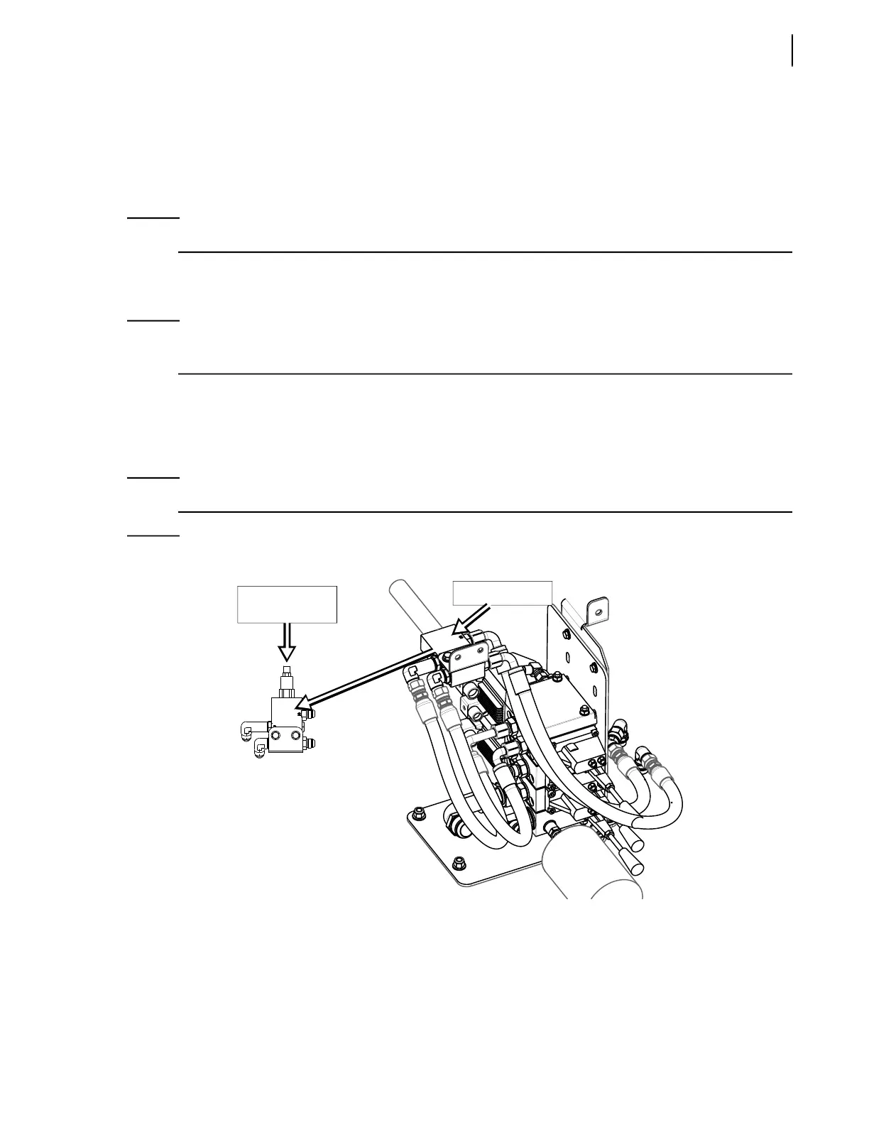
Figure 10-12
Arm in/out holding valve
To adjust the arm in/out holding valve pressure:
1. Apply all safety measures to ensure safety around the vehicle at all times.
2. Make sure that the parking brake is applied.
3. Locate one of the arm in/out holding valves (see Figure 10-12).
Holding valve
Adjustable
cartridge