Lifting Arms 403
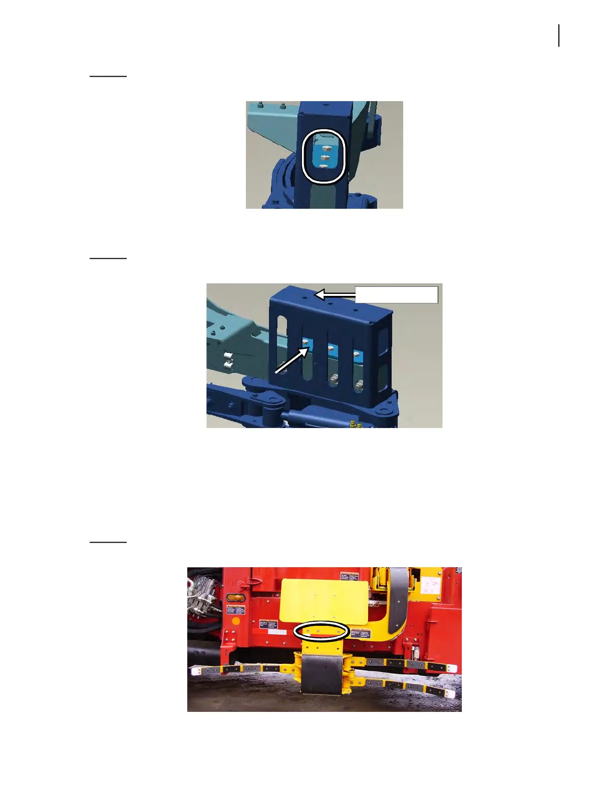
Figure 10-31
Vertical bolts
4. Raise or lower the gripper (depending on the current gripper position).
5. Reposition the plate correctly (see Figure 10-32).
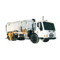
Figure 10-32
Plate
Position the plate on the top of the gripper head when the gripper is at its lower position or inside
the gripper head (see Figure 10-32) when the gripper is at its upper position.
6. Secure the plate to the arm lever using all 3 vertical bolts.
7. Reinstall all 3 horizontal bolts. Tighten them back.
Bolts in upper row if the gripper have been moved to the lower position (see Figure 10-33).
Bolts in lower row if the gripper have been moved to the upper position (see Figure 10-34).
Figure 10-33
Bolts in upper row
Top of gripper head