32i RAID/HBA adapter
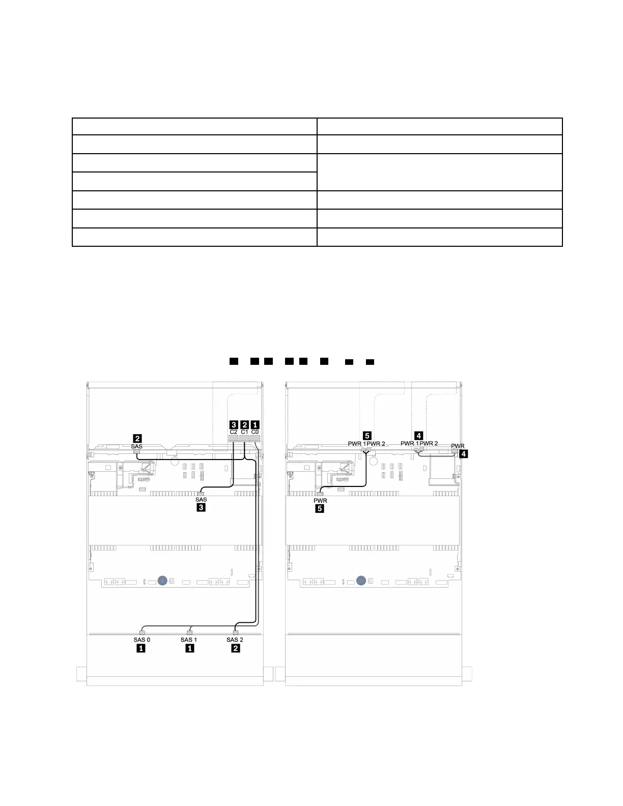
The following shows the cable connections for the 12 x 3.5-inch SAS/SATA configuration with a 4 x 3.5-inch
SAS/SATA middle backplane and a 4 x 3.5-inch/4 x 2.5-inch SAS/SATA rear backplane.
From To
Backplane 1: SAS 0, SAS 1
32i RAID/HBA
1
: C0
Backplane 1: SAS 2
32i RAID/HBA
1
: C1
Backplane 4: SAS
Backplane 5: SAS 32i RAID/HBA
1
: C2
Backplane 4: PWR Riser 1: PWR1, PWR2
Backplane 5: PWR Riser 2: PWR1, PWR2
Notes:
• For a 4 x 3.5-inch SAS/SATA rear backplane, the 32i adapter
1
is installed on PCIe slot 3.
• For a 4 x 2.5-inch SAS/SATA rear backplane, the 32i adapter
1
is installed on PCIe slot 2.
Below illustration uses the 4 x 3.5-inch SAS/SATA rear backplane as an example for cable routing. Cable
routing for the 4 x 2.5-inch SAS/SATA rear backplane is similar.
Connections between connectors:
1 ↔ 1 , 2 ↔ 2 , 3 ↔ 3 , ... n ↔ n
Figure 133. Cable routing for the 12 x 3.5-inch SAS/SATA + 4 x 3.5-inch SAS/SATA + 4 x 3.5-inch SAS/SATA
configuration with one 32i RAID/HBA adapter
Chapter 3. Internal cable routing 175

 Loading...


