Remove the rear 3.5-inch drive backplane
Use this information to remove the rear 3.5-inch 2-bay or 4-bay drive backplane.
About this task
Attention:
• Read “Installation Guidelines” on page 185 to ensure that you work safely.
• Power off the server and disconnect all power cords for this task.
• Prevent exposure to static electricity, which might lead to system halt and loss of data, by keeping static-
sensitive components in their static-protective packages until installation, and handling these devices with
an electrostatic-discharge wrist strap or other grounding system.
A video for this task is available at:
• Youtube:
https://www.youtube.com/playlist?list=PLYV5R7hVcs-DqVplE36HIvdM_sq_Auw3U
• Youku: https://list.youku.com/albumlist/show/id_59643657.html
Procedure
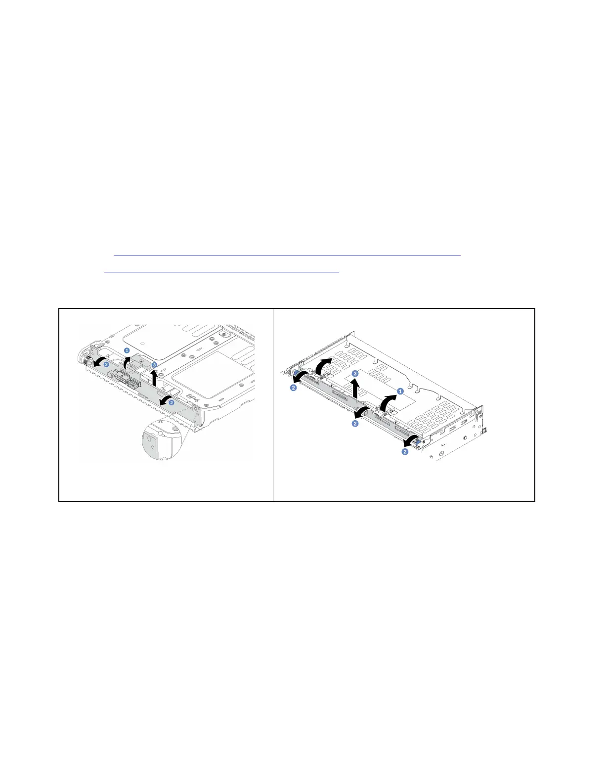
Figure 267. Removing the 2 x 3.5-inch rear drive
backplane
Figure 268. Removing the 4 x 3.5-inch rear drive backplane
Step 1. Open the release latches in the direction as shown.
Step 2. Rotate the backplane from the top to disengage it from the pins on the drive cage.
Step 3. Carefully lift the backplane out of the drive cage.
After you finish
1. Do one of the following:
• If you are replacing the backplane, install a new backplane to the drive cage.
• If you are replacing the drive cage, install the backplane to a new drive cage.
2. If you are instructed to return the defective component, follow all packaging instructions and use any
packaging materials that are provided.
Install the rear 3.5-inch drive backplane
Use this information to install the rear 3.5-inch 2-bay or 4-bay drive backplane.
338
ThinkSystem SR650 V2Maintenance Manual