Step 2. Lift the release tabs and rotate the backplane backward slightly to release it from the two pins on
the chassis.
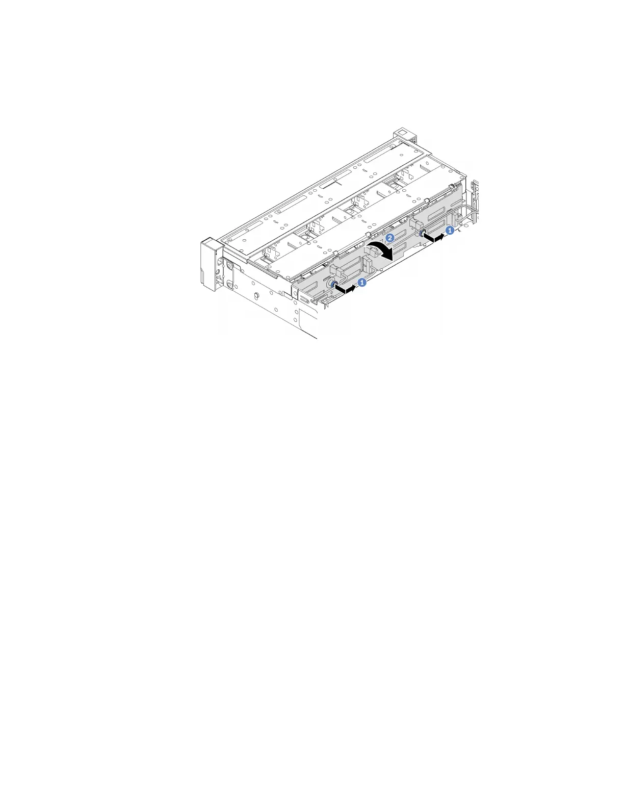
Note: Depending on the specific type, your backplane might look different from the illustration.
Figure 181. 3.5-inch drive backplane removal
a. Pull out the plungers and slightly slide the backplane to the side as shown.
b. Rotate the backplane down to release it from the four hooks on the chassis. Then, carefully lift
the backplane out of the chassis.
Step 3. Record the cable connections on the backplane and then disconnect all cables from the
backplane.
After you finish
If you are instructed to return the defective component, follow all packaging instructions and use any
packaging materials that are provided.
Install the front 3.5-inch drive backplane
Use this information to install the front 3.5-inch drive backplane.
About this task
The server supports one of the following backplanes. The installation procedure for the backplanes are the
same.
• 3.5-inch SAS/SATA 8-bay backplane
• 3.5-inch SAS/SATA 12-bay backplane
• 3.5-inch Anybay 12-bay backplane
Attention:
• Read “Installation Guidelines” on page 185 to ensure that you work safely.
• Power off the server and disconnect all power cords for this task.
Chapter 4. Hardware replacement procedures 235

 Loading...


