Configuration
8200SHB0199
7-3
SH
PRG
STP
RUN
PAR2 0VLVIMAXDBTEMP
PAR1
LOAD
SET
A
%
Hz
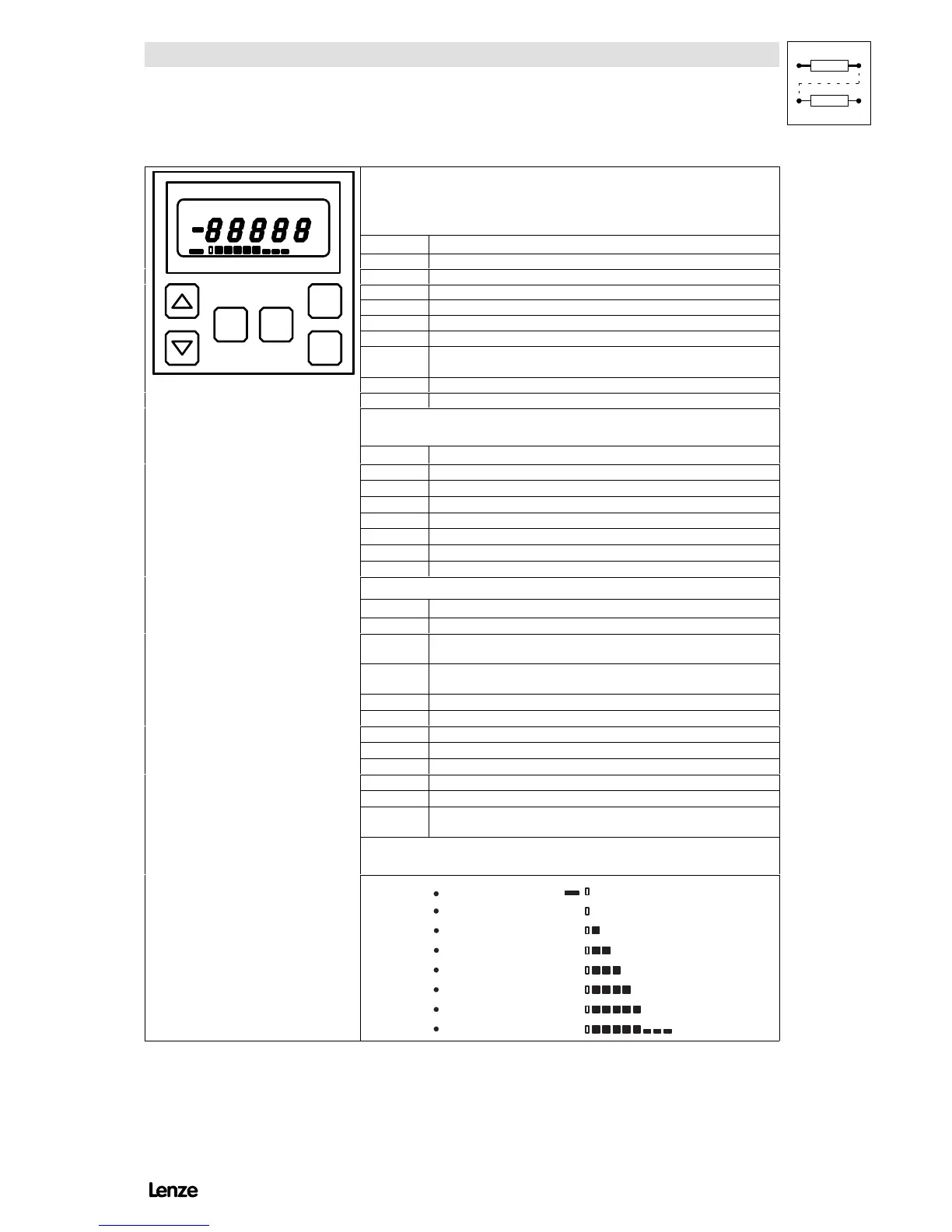
Key functions
”SH +” means:
1.Press and hold key SH.
2.Press second keyindicated.
SH
PRG
STP
RUN
PAR2 0VLVIMAXDBTEMP
PAR1
LOAD
SET
A
%
Hz
Key Function
SH
PRG
STP
RUN
PAR2 0VLVIMAXDBTEMP
PAR1
LOAD
SET
A
%
Hz
PRG Change between operating and code level
SH
PRG
STP
RUN
PAR2 0VLVIMAXDBTEMP
PAR1
LOAD
SET
A
%
Hz
SH Change between code and parameter level
SH
PRG
STP
RUN
PAR2 0VLVIMAXDBTEMP
PAR1
LOAD
SET
A
%
Hz
▲ Increase display value
SH
PRG
STP
RUN
PAR2 0VLVIMAXDBTEMP
PAR1
LOAD
SET
A
%
Hz
▼ Decrease display value
SH
PRG
STP
RUN
PAR2 0VLVIMAXDBTEMP
PAR1
LOAD
SET
A
%
Hz
SH + ▲ Increase display value rapidly
SH
PRG
STP
RUN
PAR2 0VLVIMAXDBTEMP
PAR1
LOAD
SET
A
%
Hz
SH + ▼ Decrease display value rapidly
SH
PRG
STP
RUN
PAR2 0VLVIMAXDBTEMP
PAR1
LOAD
SET
A
%
Hz
SH + PRG
Store changes
(each parameter can be stored individually before mains disconnection)
SH
PRG
STP
RUN
PAR2 0VLVIMAXDBTEMP
PAR1
LOAD
SET
A
%
Hz
STP Inhibit controller
SH
PRG
STP
RUN
PAR2 0VLVIMAXDBTEMP
PAR1
LOAD
SET
A
%
Hz
RUN Enable controller
SH
PRG
STP
RUN
PAR2 0VLVIMAXDBTEMP
PAR1
LOAD
SET
A
%
Hz
Status display
(For fault messages see chapter 8)
Display Meaning
OV Overvoltage
LV Undervoltage
IMAX Current limit exceeded
TEMP Heat sink temperature near switch-off (J
max
-10 C)
PAR1 Parameter set 1 active, PAR1 blinking: Programming possible
PAR2 Parameter set 2 active, PAR2 blinking: Programming possible
SET Setpoint input via keypad
5-digit, 7-segment display
Display Meaning
OFF Controller inhibited by a LOW signal at terminal 28
STOP
Controller inhibited (by STP key or quick stop function or field frequency
f
d
=0Hz)
AS_LC
Autostart-Lockout, controller will only be enabled after a low-high edge at
terminal 28.
STO The parameter will be stored.
dC_b DC injection brake active
LU Undervoltage
SET1 Parameter set 1 will be overwritten with the factory setting.
SET2 Parameter set 2 will be overwritten with the factory setting.
rEAd1 Parameter set 1 will be overwritten with the data of the operating module.
rEAd2 Parameter set 2 will be overwritten with the data of the operating module.
STOE
The parameter sets PAR1 and PAR2 will be transferred to the operating
module.
Bar-graph display
The bottom line of the LCD shows the controller load:
LO A D
LO A D
LO A D
LO A D
LO A D
generative
no
20%
40%
100%
80%
60%
160%
LO A D
LO A D
LO A D
load
overload
load
load
load
load
load
load
FIG 7-1 8201BB operating modules - functions, displays
Artisan Technology Group - Quality Instrumentation ... Guaranteed | (888) 88-SOURCE | www.artisantg.com