Installation
8200SHB01994-38
4.2.8 Control connections
4.2.8.1 Control cables
- Connect the control cables to the screw terminals:
Max. permissible cable cross-section Tightening torques
2.5 mm
2
0.5 ... 0.6 Nm (4.4 ... 5.3 lbin)
- We recommend the unilateral screening of all cables for analog signals to
avoid signal distortion.
- Connect the screens of the control cables
- 820X:
To the front FAST-ON connector
- 8211 - 8214:
To the front FAST-ON connector
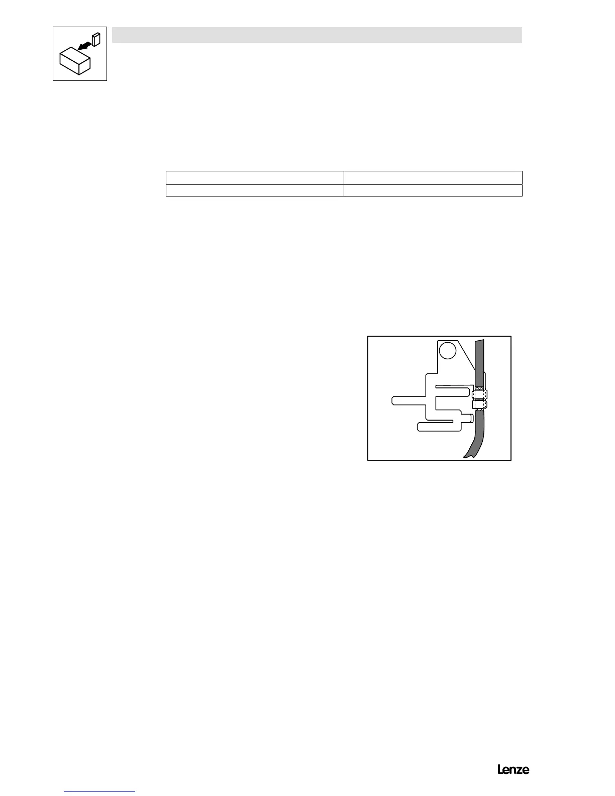
- 8215 - 8218:
To the front metal surface (screw length max. 12 mm).
- 822X, 824X
With the screen sheet to the front
metal surface
(screw length max. 12 mm).
- If the control cables are interrupted (terminal strips, relays), the screens
must be reconnected over the shortest possible distance.
- Connect the fixing screw of the setpoint potentiometer to PE.
- Motor-temperature monitoring
(Optionally for 820X/821X, as standard for 822X/824X)
- If possible, separate the cables from the motor cable.
4.2.8.2 Assignment of the control terminals
Protection against contact - 820X/821X
- The control terminals have a basic isolation (single insulating distance).
- If protection against contact is required,
- a double insulating distance must be provided,
- the components to be connected must have a second insulating distance.
Protection against contact - 822X/824X
- The control terminals are separated (VDE 0160, EN50178), the protection
against contact is ensured without additional measures.
Artisan Technology Group - Quality Instrumentation ... Guaranteed | (888) 88-SOURCE | www.artisantg.com