Assembly output objects (outputs)
Assembly output objects are usually used to enable the inverter (Adapter) and dene a speed
or torque setpoint.
Depending on the data length dened by the PLC (Scanner) the memory map of the I/O data
may vary in size.
In case of assembly output objects, a 32-bit-run/idle header is assumed. When the assemblies
are mapped, this header is inserted automacally into the data ow by most of the Allen-
Bradley PLC/SLC devices. For this purpose, no adaptaons are required.
If your PLC does not support the 32-bit run/idle header, complement the output image by a
leading 32-bit header. Set the data in the header to 0.
Bit 0 of the header can be dened in the process image of your PLC:
•
State 0: Idle mode
•
State 1: Run mode
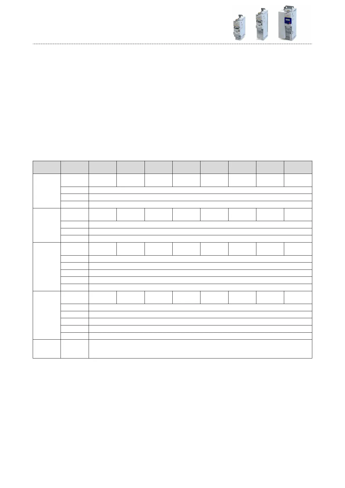
Structure of the output objects
Aribute
(Instance ID)
Byte Bit 7 Bit 6 Bit 5 Bit 4 Bit 3 Bit 2 Bit 1 Bit 0
20
(0x14)
0 FaultRst
RunFwd
(CW)
1
2 Speed Reference (low byte)
3 Speed Reference (high byte)
21
(0x15)
0 NetRef NetCtrl FaultRst
RunRev
(CCW)
RunFwd
(CW)
1
2 Speed Reference (low byte)
3 Speed Reference (high byte)
22
(0x16)
0 FaultRst
RunFwd
(CW)
1
2 Speed Reference (low byte)
3 Speed Reference (high byte)
4 Torque Reference (low byte)
5 Torque Reference (high byte)
23
(0x17)
0 NetRef NetCtrl FaultRst
RunRev
(CCW)
RunFwd
(CW)
1
2 Speed Reference (low byte)
3 Speed Reference (high byte)
4 Torque Reference (low byte)
5 Torque Reference (high byte)
110
(0x6E)
0
...
31
Custom Output
Conguring the network
EtherNet/IP
Objects
326