LIST OF FIGURES
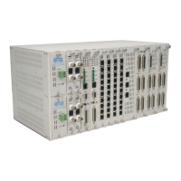
Figure 1-1 Loop-IP 6610 ------------------------------------------------------------------------------------------------------------1
Figure 1-2 Application Illustration ------------------------------------------------------------------------------------------------2
Figure 1-3 Mobile ATM Solution --------------------------------------------------------------------------------------------------2
Figure 1-4 Ethernet to Data Transmission Solution --------------------------------------------------------------------------2
Figure 2-1 Loop-IP 6610 Front Panel (Single Ethernet)---------------------------------------------------------------------6
Figure 2-2 Loop-IP6610 DTE Front Panel (Four Ethernet) ---------------------------------------------------------------6
Figure 2-3 Loop-IP6610 DTE Front Panel (Single Ethernet)---------------------------------------------------------------6
Figure 2-4 Loop-IP 6610 DTE Rear Panel (EIA 530) with AC Power (1 Port)-----------------------------------------6
Figure 2-5 Loop-IP 6610 DTE Rear Panel (EIA 530) with DC Power (1 Port)-----------------------------------------6
Figure 2-6 Loop-IP 6610 DTE Rear Panel (EIA 530) with AC Power (4 Port)-----------------------------------------6
Figure 2-7 Loop-IP 6610 DTE Rear Panel (EIA 530) with DC Power (4 Port)-----------------------------------------6
Figure 2-8 Loop-IP 6610 Rear Panel Views-----------------------------------------------------------------------------------7
Figure 2-9 Main Board Jumper Selection---------------------------------------------------------------------------------------6
Figure 2-10 Daughter Board Jumper3 Selection------------------------------------------------------------------------------6
Figure 3-1 SNMP Connection---------------------------------------------------------------------------------------------------- 16
Figure 4-1 DS1 Loopback Block Diagram ------------------------------------------------------------------------------------ 19
Figure 4-2 E1 Loopback Block Diagram -------------------------------------------------------------------------------------- 20
Figure 4-3 DTE Loopback Block Diagram ------------------------------------------------------------------------------------ 20
Figure 5-1 VT-100 Monitor Connection---------------------------------------------------------------------------------------- 22
Figure 6-1 DHCP Application ---------------------------------------------------------------------------------------------------- 27
Figure 6-2 DHCP Relay Setup--------------------------------------------------------------------------------------------------- 32
Figure 7-1 Frame Relay Application ------------------------------------------------------------------------------------------- 34
Figure 8-1 IP Routing Setup ----------------------------------------------------------------------------------------------------- 38
Figure 9-1 Setting Up IP Routing with Network Address Translation -------------------------------------------------- 43
Figure 10-1 IP Routing Setup for Packet Filtering Mode ----------------------------------------------------------------- 47
Figure 11-1 Port Forwarding - Virtual Service Application --------------------------------------------------------------- 51
Figure 12-1 QoS Application----------------------------------------------------------------------------------------------------- 56
Figure 13-1 Remote Bridge Mode Setup-------------------------------------------------------------------------------------- 58
Figure 15-1 Normal STP Link---------------------------------------------------------------------------------------------------- 66
Figure 15-2 Restored STP Link ------------------------------------------------------------------------------------------------- 67
Figure 16-1 VLAN Application #1----------------------------------------------------------------------------------------------- 73
Figure 16-2 VLAN Application #2----------------------------------------------------------------------------------------------- 74
Figure 17-1 Transparently Conveying VLAN-enabled Customer Traffic---------------------------------------------- 83
Figure 17-2 802.1Q Encapsulation --------------------------------------------------------------------------------------------- 83
Figure 17-3 802.1ad (QinQ) encapsulation----------------------------------------------------------------------------------- 83
Figure 17-4 SVLAN Setup Diagram-------------------------------------------------------------------------------------------- 86
Figure 18-1 PPP application ----------------------------------------------------------------------------------------------------- 87
Figure 19-1 AT modem application -------------------------------------------------------------------------------------------- 89
Figure 20-1 Firmware/Configuration Up/Download with TFTP Server on LAN Side------------------------------- 91
Figure 20-2 Firmware/Configuration Up/Download with TFTP Server on Outside Network --------------------- 92
Figure 23-1 VT-100 Terminal -------------------------------------------------------------------------------------------------- 162
Figure 24-1 Layer 3 Media Converter Application------------------------------------------------------------------------ 164
Figure 24-2 Mobil ATM Application with Fixed IP ------------------------------------------------------------------------ 165
Figure 24-3 Mobil ATM Application with Dynamic IP -------------------------------------------------------------------- 166