Control panel
- 40 -
04.19909.1709.9-05
13 Control panel
32 37 38 39 40 41 42 43 45 34 46 47
1
48 49 50 51 33
57
59
52
35
53
2021222324252628
1
29
1
30
1
3127
58
56
55
36
54
B A
C
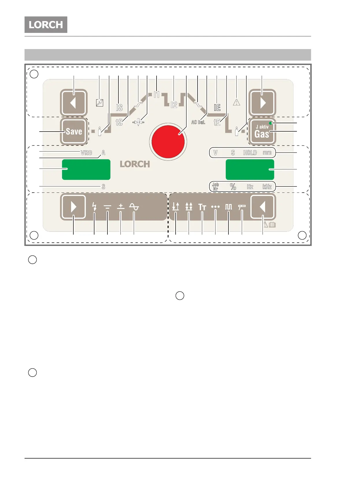
Abb. 8: T-series AC/DC ControlPro control panel
A
Mode
20 The mode button
selects the mode.
21 LED Electrode
lights up if you select the electrode mode.
22 LED Pulse
lights up if you select the pulse mode.
23 LED Spots
lights up if you select the spots mode.
24 LED Tiptronic
lights up if you select the tiptronic mode.
25 LED 4-stroke
lights up if you select the 4-stroke mode.
26 LED 2-stroke
lights up if you select the 2-stroke mode.
B
Current mode
27 The current mode button
selects the welding current type DC, AC, with or
without HF ignition and MACS.
28
1
LED Alternating Current (AC)
lights up if you select the AC welding process.
29
1
LED Direct current +
lights up if you select operating mode DC+ (posi-
tive polarity on the connection bush 3)
1)
Only for AC/DC
30
1
LED DC -
lights up if you select operating mode DC - (nega-
tive polarity on the connecting bush 3)
31 LED HF
lights up if you select the function HF, for touch-
less ignition.
C
Welding parameters
32 The selection button on the left
allows you to select the individual welding param-
eters.
33 The selection button on the right
allows you to select the individual welding param-
eters.
34 The knob
allows you to adjust the welding parameters.
35 7-segment display
displays the welding parameters and tiptronic job
no.
36 7-segment display
displays parameter codes and the welding pa-
rameter ampere or seconds.
37 LED Remote control
lights up with an activated remote control
38 LED Gas pre-ow time
lights up for selected parameters. The gas pre-
ow time can be changed with knob (34).
 Loading...

