Starting up
- 42 -
04.19909.1709.9-05
14 Starting up
14.1 Electrode welding process
 Use button 20 to select the electrode mode (LED
electrode 21 lights up).
 Use the selection buttons 32 or 33 to select the pa-
rameter electrode diameter (LED 42 lights up).
 Use knob 34 to set the desired electrode diameter.
 Use the current mode selection button 27 to set the
desired current mode.
 Use the selection buttons 32 or 33 to select the pa-
rameter main current I1 (LED 43 lights up).
 Use the rotary knob 34 to set the desired current
intensity. If the current intensity does not match the
selected electrode diameter then the warning LED
lights 50 up. Nevertheless, it is possible to weld.
9 Your welding machine is now ready for use.
Electrode diameter [mm]
Recommended current
intensity [A]
1,5 20 - 40
2,0 35 - 60
2,5 45 - 100
3,2 75 - 140
4,0 130 - 190
5,0 180 - 260
Heed the electrode manufacturer’s instruc-
tions.
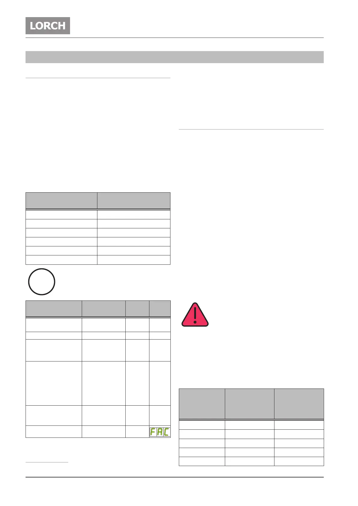
Parameter Range
Factory
setting
LED/
Code
Hotstart IS 5 - 200 %
of main current
125 39
Hotstart time tS 0 - 20 sec. 1 40
Electrode diameter
2,5 42T 180, T 220 1,5 - 4,0
T 250, T 300 1,5 - 5,0
Main current I1
100 43
T 180 10 - 150 A
T 220 AC/DC 10 - 170 A
T 220 DC 10 - 180 A
T 250 10 - 200 A
T 300 10 - 200 A
AC-balance
1
10 - 90 %
positive welding
current
35 47
AC-frequency
1
30 - 200 Hz 60
Tab. 2: Main parameters
1)
Only for AC/DC
The factory setting values are optimised thanks to auto-
matic parameters.
You can use these factory settings unchanged for most
welding jobs.
Further ne adjustment facilities can be found in Chapter
„14.3 Secondary parameters“ on page 44.
14.2 TIG welding process
 Select the desired mode with button 20.
– 2-stroke mode (LED 26 lights up).
– 4-stroke mode (LED 25 lights up).
– Spots mode (LED 23 lights up, only for 2-stroke).
– 2-stroke pulse mode (LED 22 and LED 26 light
up).
– 4-stroke pulse mode (LED 22 and LED 25 light
up).
 Use the selection buttons 32 or 33 to select the pa-
rameter electrode diameter (LED 42 lights up).
 Use knob 34 to set the desired electrode diameter.
 Use the current mode selection button 27 to set the
desired current mode.
 Use the selection buttons 32 or 33 to select the pa-
rameter main current I1 (LED 43 lights up).
 Use the rotary knob 34 to set the desired current in-
tensity. If the current intensity is not appropriate for
the selected tungsten electrode diameter, LED 50
lights up. Nevertheless, it is possible to weld.
9 Your welding machine is now ready for use.
HF ignition
Danger due to electric shock!
If function HF-ignition (31) is selected,
a high ignition voltage is present at the
torch.
Never touch the welding electrode or parts
conducting welding current when the de-
vice is switched on.
HF ignition is a contactless ignition brought about by
high-voltage impulses.
 Using the current type button, select 27 HF ignition
(LED HF 31 lights up).
Electrode
diameter
[mm]
Recommended
current inten-
sity DC
[A]
Recommended
current inten-
sity AC
[A]
1,0 3 - 40 5 - 30*
1,6 15 - 130 20 - 90*
2,0 45 - 180 45 - 135*
2,4 70 - 240 70 - 180*
3,2 140 - 320 130 - 250*
i
 Loading...

