Starting up
- 43 -
04.19 909.1709.9-05
Electrode
diameter
[mm]
Recommended
current inten-
sity DC
[A]
Recommended
current inten-
sity AC
[A]
4,0 220 - 450 200 - 320*
*) Depending on the type of electrode and AC-Balance
parameter setting
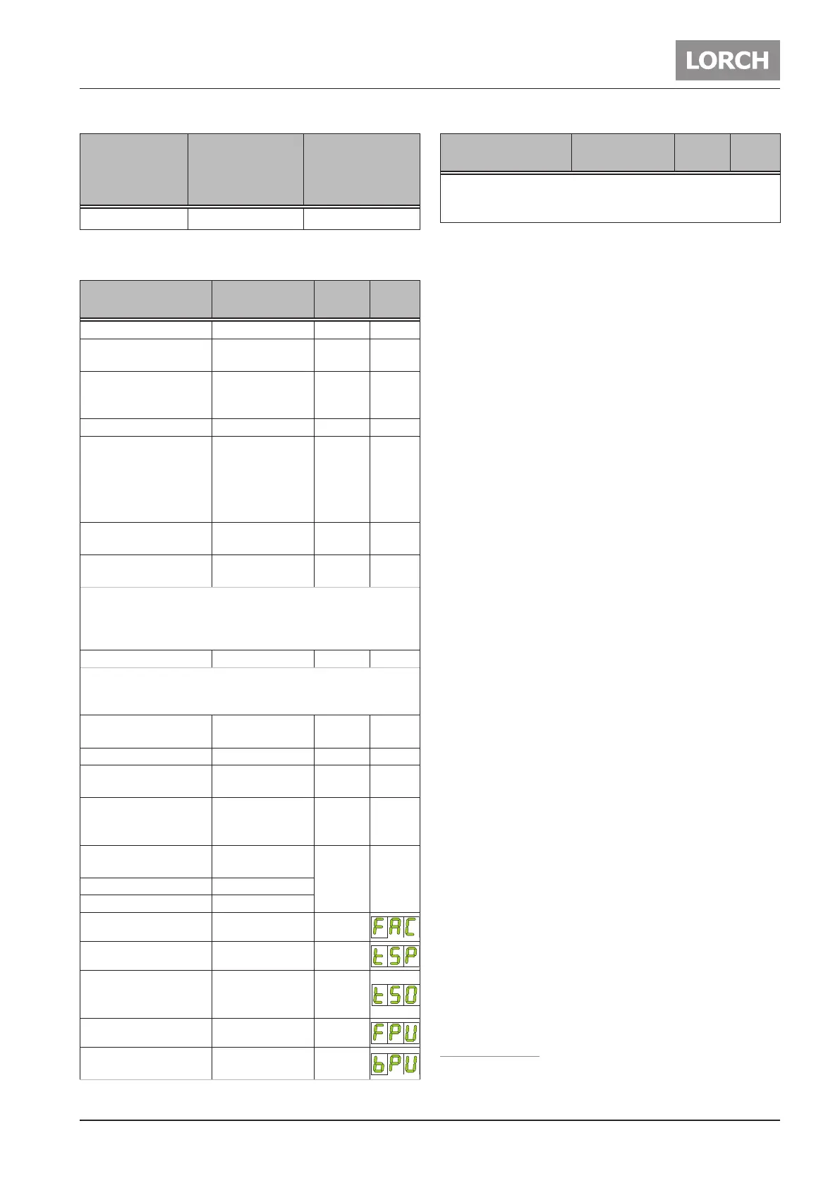
Parameter Range
Factory
setting
LED/
Code
Gas pre-ow time 0,1 - 10 sec. 0,1 38
Start current IS
5 - 200 % of
main current
50 39
Start current time tS
(only for 2-stroke
mode)
0 - 20 sec. 0,1 40
Upslope 0 - 99 % 5 41
Main current I1
100 43
T 180 3 - 180 A
T 220 3 - 220 A
T 250 5 - 250 A
T 300 5 - 300 A
Second current I2
1 - 200 % of
main current
50 45
MACS-DC current
1, 3
1 - 200 % of
main current
50 45
Indicates the percentage ratio of the welding current
strength direct current (DC) to the main current I1.
If the value set is 50, the DC current strength is 50% of the
main current I1.
Downslope 0 - 500 % 20 46
A synchronisation takes place in the DC pulse operating
mode with feed or control The current reduction always
begins with I2 independent of the current status I1 or I2.
Final current IE
5 - 200 % of
main current
25 48
Final current time tE 0 - 20 sec. 0,2 49
Gas post-ow time
correction
20 - 500 % 100 51
AC-balance
1
10 - 90 %
positive welding
current
35 47
Tungsten electrode
diameter
2,4 42
T 180, T 220 1,0 - 3,2 mm
T 250, T 300 1,0 - 4,0 mm
AC-frequency
1
30 - 200 Hz 60
Spot welding time 0,01 - 10 sec. 1
Spot welding time Off
(only with interval spot
welding “On”)
0,09 - 60 sec. 1
Pulse frequency 0,2 - 2000 Hz 5
Pulse duty factor
1 - 99 % Main
current I1
50
Parameter Range
Factory
setting
LED/
Code
Indicates the percentage ratio between main current I1 and
auxiliary current I2. If the value set is 30, the ratio is 30 %
I1 to 70 % I2.
Tab. 3: Main parameters
The factory setting values are optimised thanks to auto-
matic parameters.
You can use these factory settings unchanged for most
welding jobs.
Further ne adjustment facilities can be found in Chapter
„14.3 Secondary parameters“ on page 44.
1)
Only for AC/DC
2)
Only in operating mode Electrode
3)
Only in operating mode TIG
 Loading...

