Multi-Function Relay Setting Details
Set the Relay 1 output item.
Set the Relay 2 output item.
Set output terminal and relay functions according to OU.57 (FDT
Frequency), OU.58 (FDT Band) settings and fault trip conditions.
Detects inverter output frequency reaching the
user set frequency. Outputs signal when the
conditions below are satisfied.
Absolute value(set frequency–output
frequency) < detected frequency width/2
When detected frequency width is 10 Hz, FDT-
1 output is as shown in the graph below.
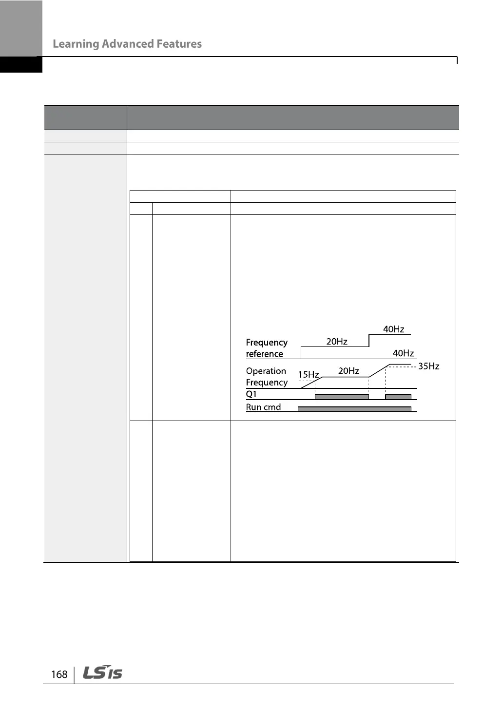
Outputs a signal when the user set frequency
and detected frequency (FDT Frequency) are
equal, and fulfills FDT-1 condition at the same
time.
[Absolute value (set frequency-detected
frequency) < detected frequency
width/2]&[FDT-1]
Detected frequency width is 10 Hz. When the
detected frequency is set to 30 Hz, FDT-2
output is as shown in the graph below.