Outputs signal when the operation frequency
below meets the conditions.
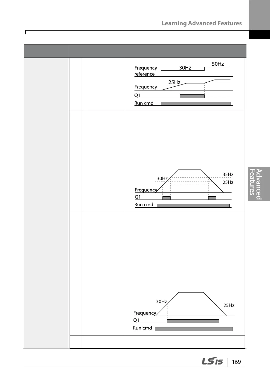
Absolute value(output frequency–operation
frequency) < detected frequency width/2
Detected frequency width is 10 Hz. When the
detected frequency is set to 30 Hz, FDT-3
output is as shown in the graph below.
Output signal can be separately set for
acceleration and deceleration conditions.
• In acceleration: Operation frequency
Detected frequency
• In deceleration: Operation frequency >
(Detected frequency–Detected frequency
width/2)
Detected frequency width is 10 Hz. When the
detected frequency is set to 30 Hz, FDT-4
output is as shown in the graph below.
Outputs a signal at motor overload.