Step 5 PNP/NPN Mode Selection
The G100 inverter supports both PNP (Source) and NPN (Sink) modes for sequence
inputs at the terminal. Select an appropriate mode to suit requirements using the
PNP/NPN selection switch (SW1) on the control board. Refer to the following
information for detailed applications.
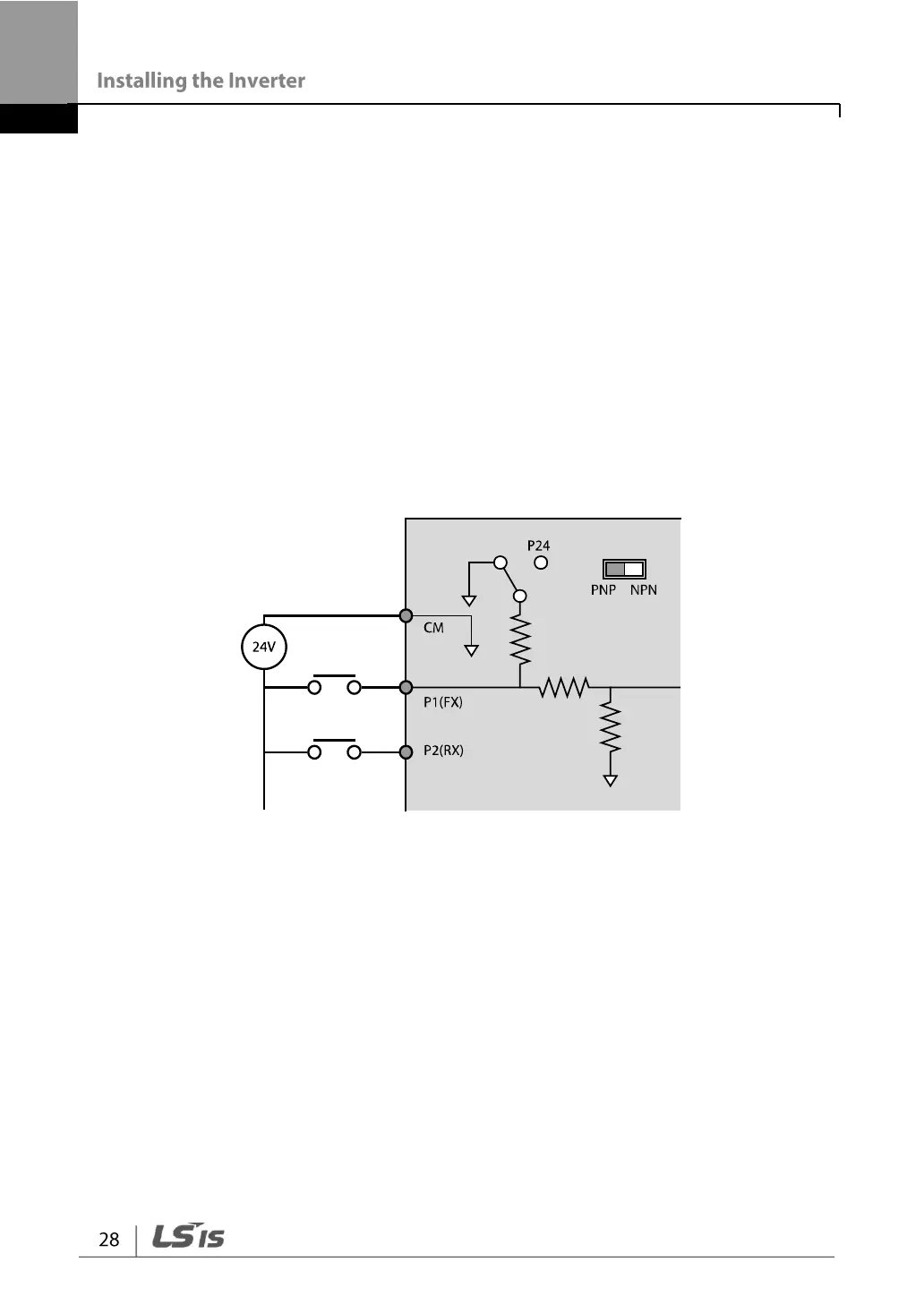
PNP Mode (Source)
Select PNP using the PNP/NPN selection switch (SW1). CM is the common ground
terminal for all analog inputs at the terminal, and P24 is 24 V internal source. If you
are using an external 24 V source, build a circuit that connects the external source (-)
and the CM terminal.