214713 35 Revision A
Figure 3.62: Pin Support
6. Install two M20 x 65 bolts (A), hardened washers,
and nuts.
7. Temporarily install bolts (B) to help align the assembly.
Figure 3.63: Pin Installation
8. Rotate pin (A), until hole in pin aligns with holes in
welded collar (B). Insert pin (C) (MD #19958) through
the collar and pin.
9. Insert cotter pin (D) (MD #18608) and bend over the
legs to secure it.
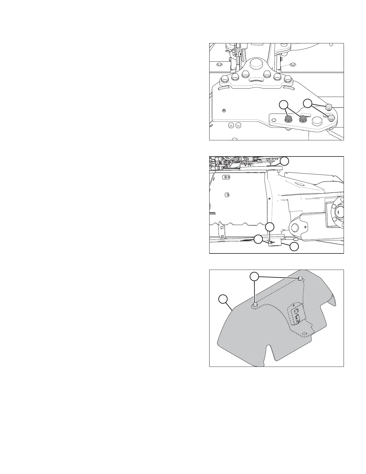
Figure 3.64: Cover Assembly
10. Retrieve cover assembly (B) from the shipping location.
11. Remove two bolts (A) from the cover assembly (B).
Retain bolts and cover for installation later.
ASSEMBLING THE DISC MOWER (WITH OR WITHOUT THE DEALER-INSTALLED TRANSPORT)