214713 36 Revision A
1022605
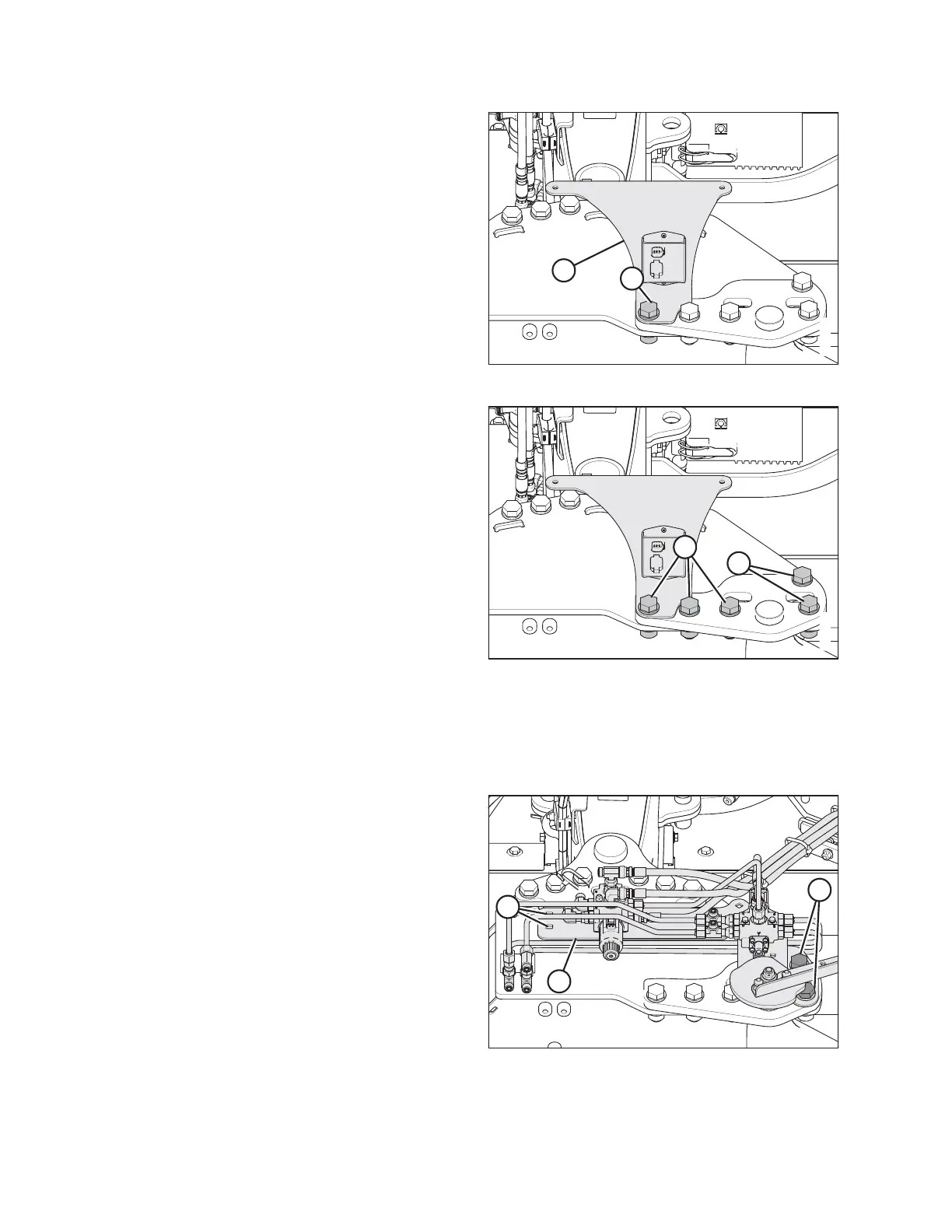
A
B
Figure 3.65: Cover Support
12. Install cover support (B).
13. Secure cover support (B) in place with one M20 x 65
bolt (A), hardened washer, and nut.
1022606
A
B
Figure 3.66: Cover Support
14. Torque bolts (A) to 461 Nm (340 lbf·ft).
15. Remove and retain bolts (B).
Installing Transport Valve
NOTE:
Cover support bracket removed from illustrations for clarity.
1016394
A
B
C
Figure 3.67: Selector Valve
1. Retrieve valve assembly (A) from the pallet.
2. Position valve assembly (A) on the carrier hitch pin
plate as shown.
3. Install two M20 x 65 bolts (B), hardened washers,
and nuts.
4. Retrieve two M10 x 20 bolts from the shipping bag and
install bolts at location (C) with threads facing up. Install
nuts, but do not tighten.
5. Torque bolts (B) to 461 Nm (340 lbf·ft).
ASSEMBLING THE DISC MOWER (WITH OR WITHOUT THE DEALER-INSTALLED TRANSPORT)