7-16
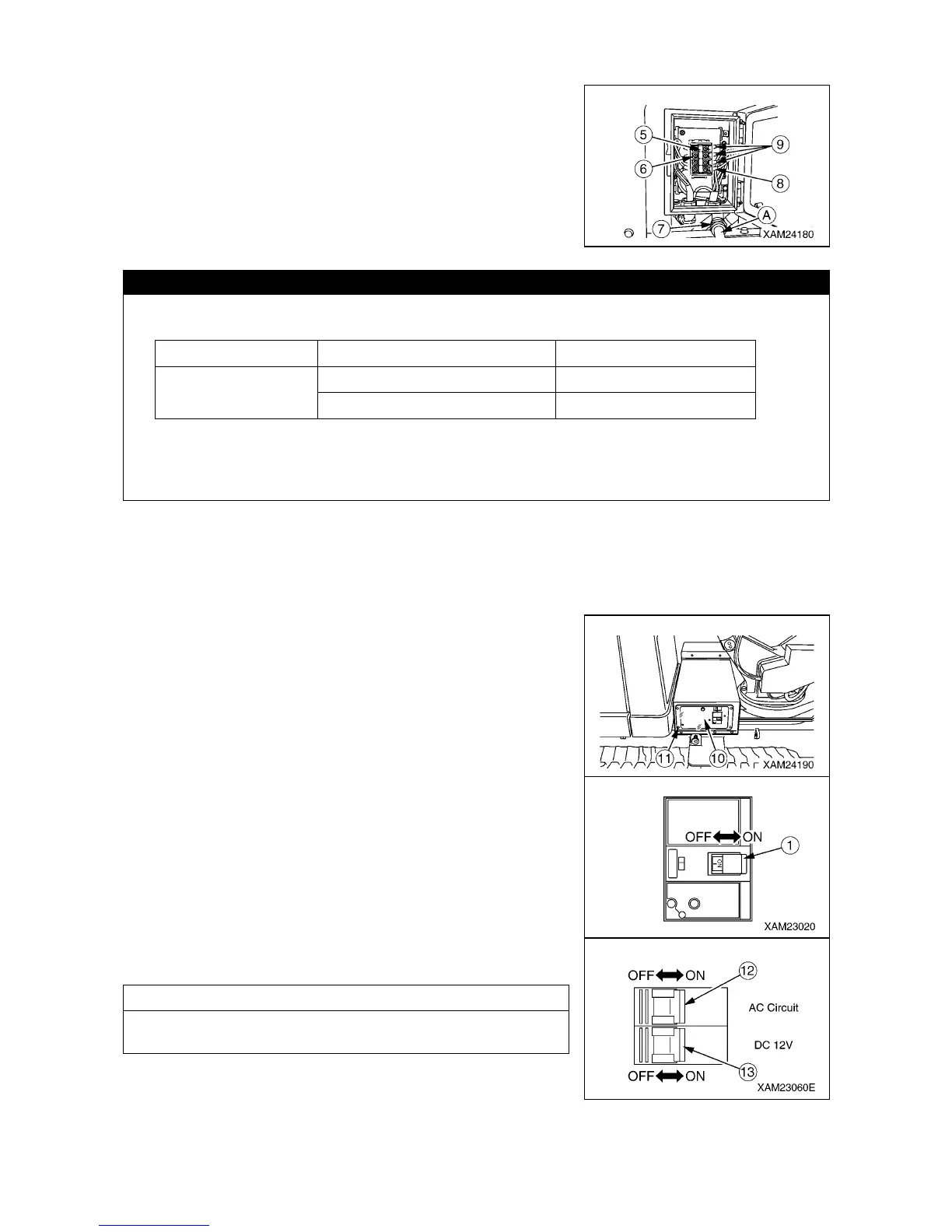
3. Remove the cover (6) of the terminal block (5) in the power
supply box, holding the top and bottom of the cover (6) with
fingers and pulling it toward you.
4. Draw the machine specifications-compliant cabtyre cable (A)
through a hole of the cable ground (7) at the bottom of the power
supply box to connect it to the terminal block (5).
CAUTION
• The length of a cabtyre cable varies with cable specifications. Any cable length should
conform to values listed below.
• The ground cable (8) of the cabtyre cable must be properly connected to the “PE terminal” on
the terminal block . Inverter-driven three cables (9) other than the ground cable are capable of
being connected to any of "L1, L2, and L3 terminals”.
5. Upon completion of connection of the power supply box cabtyre cable (A), replace the cover (6) of the
terminal block (7) and close the door (3) of the power supply box (2).
6. Move and connect the cable terminal block to the power supply equipment breaker without undue strain
on the cabtyre cable (A).
7. Turn ON the power supply equipment breaker.
8. Remove the four mounting screws (11) and remove the
protective cover (10).
9. Turn ON the breaker (1).
10. Turn ON the AC circuit power switch (12) and DC12V power
switch (13).
NOTES
No safety hazard is posed even if the AC circuit power switch
(12) and DC12V power switch (13) remain ON.
11.Replace the protective cover (10) to the original position and
securely tighten four mounting screws (11).
Motor voltage (V) Cable spec. (sq) Cable length (m)
380, 400
3.5 20
5.5 40