3-84
2.14.1 NAME OF OUTRIGGER COMPONENTS
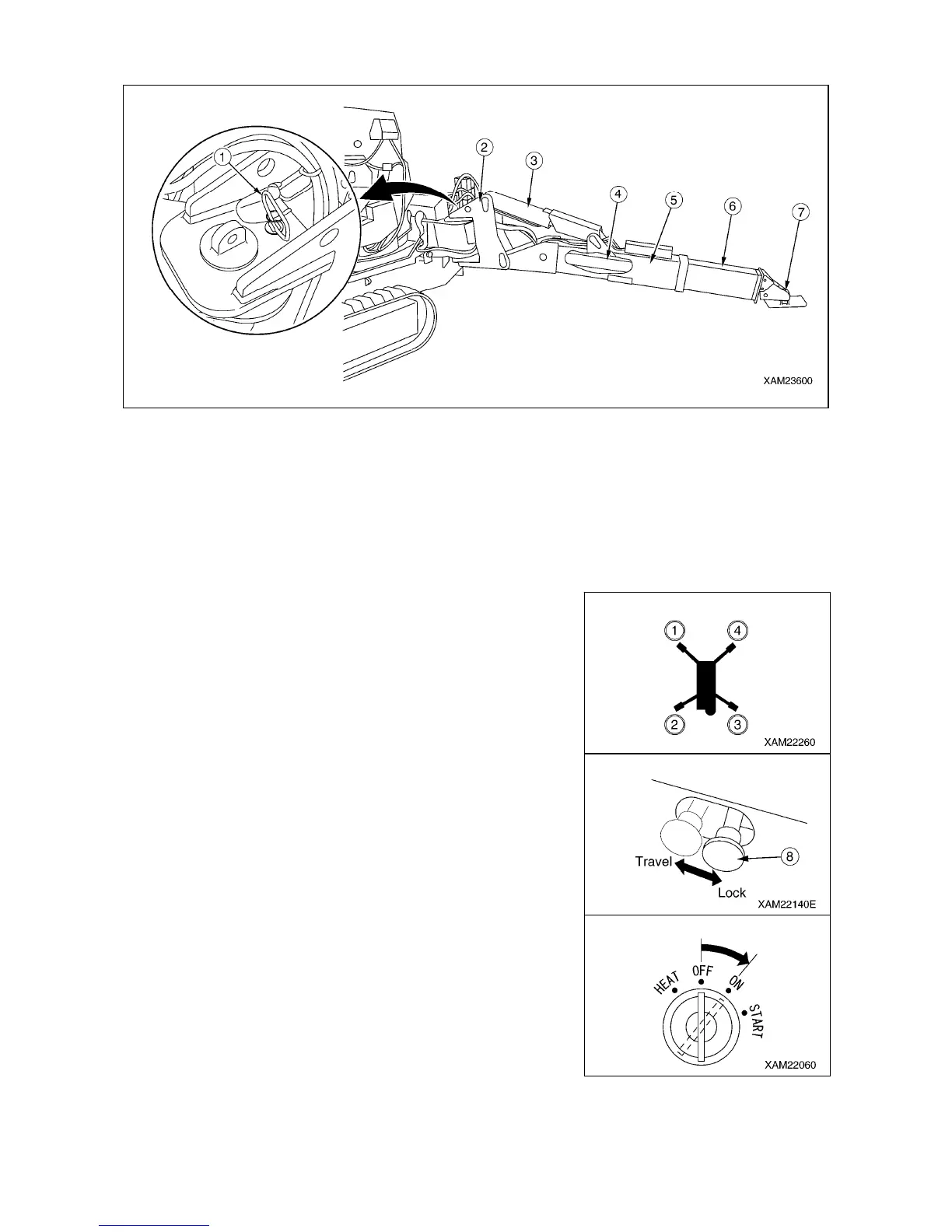
(1) Position pin
(2) Rotary
(3) Outrigger setting cylinder
(4) Outrigger extension cylinder
(5) Outer box
(6) Inner box
(7) Outrigger adapter (Tray)
2.14.2 OUTRIGGER SETTING OPERATION
[1] TASKS TO BE PERFORMED UPON ENGINE STOP
There are four outriggers installed to the machine.
Although the setting method is described for just one outrigger
(outrigger (4)), set the other three outriggers in the same way.
1. Operate the traveling lock lever (8) to the “LOCK” position.
2. Turn the starter switch to the “ON” position.