94
Magtrol Model DSP7000 Dynamometer ControllerChapter 8 – Optional Equipment
operation
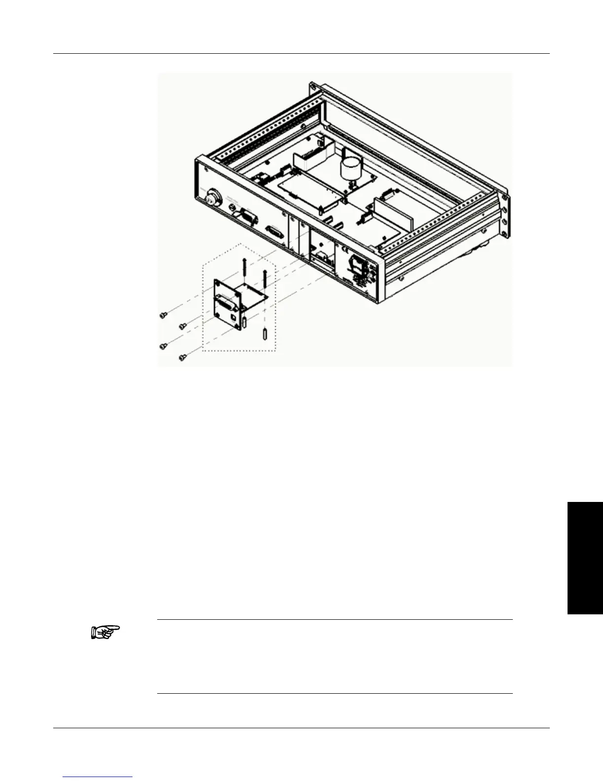
Figure 8–10 GPIB Card Installation
4. Mount the two standoffs and the two socket head cap screws onto the main board. Use four
Philips pan head screws to secure the GPIB card into the rear panel of the DSP7000.
5. Replace the top cover of the DSP7000 and secure with four Philips pan head screws.
8.2.2
aBouT THe gpiB inTerfaCe
(General Purpose Interface Bus)
Magtrol instruments use the GPIB (IEEE-488 Standard) for computer-to-instrument interfacing
because:
• TheGPIBparallelinterfaceisfasterthanserialinterfaces.
• TheGPIBenablestesterstoaccessupto15instrumentsononeport.Becausetypicalmotor
testing requires that at least five separate parameters be synchronized, a system of easy, fast
access to more than one instrument is essential.
• TheGPIBhasrigiddataformattingandhardwarestandards.Thesestandardshelptoensure
that all functions will work properly when the hardware and software are installed.
Note: The GPIB interface is not standard on most computers. An interface
card and driver software must be installed. An IEEE-488 cable
must also be installed between the computer and the DSP7000.
Magtrol recommends National Instruments Corporation hardware
and software.

 Loading...