20
Magtrol Model DSP7000 Dynamometer ControllerChapter 3 – Installation/Configuration
SETUP
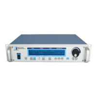
3.1.2 Main Menu
When the DSP7000 is completely powered up and ready for use, the main menu will appear on the
display.
BRAKE STATUS SET POINT SET POINT PID
TORQUE SPEED USER DISPLAY
0.000 W
OFF
0.000 OZ.IN
0000
0%
0% 0%
0
Figure 3–4 Main Menu
3.2 INSTRUMENTATION SETUP (TORQUE)
The DSP7000 has the ability to support a combination of up to two testing instruments with
independent or tandem configurations.
Note: In the TSC1 (WB/PB) and TSC2 (WB/PB) combination, the
instruments can be configured independently or as a tandem unit.
The setup of your unit will depend on which option you choose. The following sections will illustrate
and outline the hardware connection and software configurations needed to begin your testing, based
on your selection. For additional reference, see Appendix C: Front Panel/Display Menu Flow Charts.
Each channel of the DSP7000 can support the following dynamometers:
TSC 1/TSC 2
HD
WB
PB
TM/TF
HD5

 Loading...