13
Magtrol Model DSP7000 Dynamometer Controller
Chapter 2 – Controls
GENERAL
INFORMATION
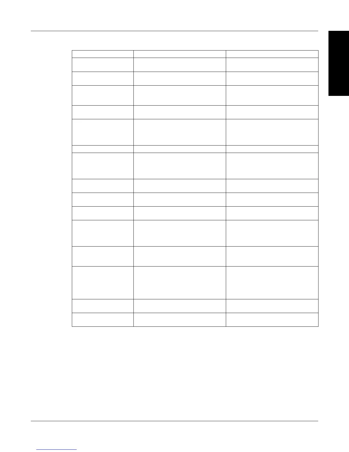
2.2.3.2 Double-Function Buttons
Button To Use Function
DISPLAY BOTH Press SHIFT and release; then
press this button.
Displays both TSC1 and TSC2
measurments.
TSC Press this button Switches between TSC1 and
TSC2 setup.
SETUP Press SHIFT and release; then
press this button.
Displays setup menu for
dynamometer, autotune, I/O,
system, and user.
OPEN LOOP Press this button Enables Open Loop mode (if brake
is off).
POWER UNITS Press SHIFT and release; then
press this button.
Sets desired unit of power. Press
UP or DOWN button to see
options. Press SHIFT to enable
option.
BRAKE ON/OFF Press this button. Turns brake ON or OFF.
TORQUE UNITS Press SHIFT and release; then
press this button.
Sets desired unit of measure.
Press UP or DOWN button
to see options. Press SHIFT to
enable option.
TORQUE SET Press this button. Enables adjustment of set point for
torque loading.
MAX SPEED Press SHIFT and release; then
press this button.
Sets the speed range of the
Controller.
SPEED SET Press this button. Enables adjustment of set point for
speed loading.
SCALE P Press SHIFT and release; then
press this button.
Turns auxiliary/torque transducer
display ON or OFF. Enables
adjustment of scale factors for
torque and speed DAC’S.
SCALE I Press SHIFT and release; then
press this button.
Adjusts GPIB primary address and
RS-232 baud rate. Also adjusts
display contrast.
SCALE D Press SHIFT and release; then
press this button.
Provides options to set maximum
power, dynamometer settings
(input units, maximum torque and
scale factor), speed encoders and
alarms.
TARE/LEFT
Press SHIFT and release; then
press this button.
RESET TARE/
RIGHT
Press SHIFT and release; then
press this button.
2.3 VACUUM FLUORESCENT DISPLAY (VFD)
The VFD provides information about the control functions, the motor under test, and an auxiliary
input device or In-Line Torque Transducer (if connected). The displays, from left to right, are:
 Loading...