35
Magtrol Model DSP7000 Dynamometer Controller
Chapter 3 – Installation/Configuration
SETUP
BRAKE STATUS SET POINTSET POINTPID
TORQUE SPEED USER DISPLAY
SOURCE
XXXX
PPR
XX
SPEED ALARM
XXXX
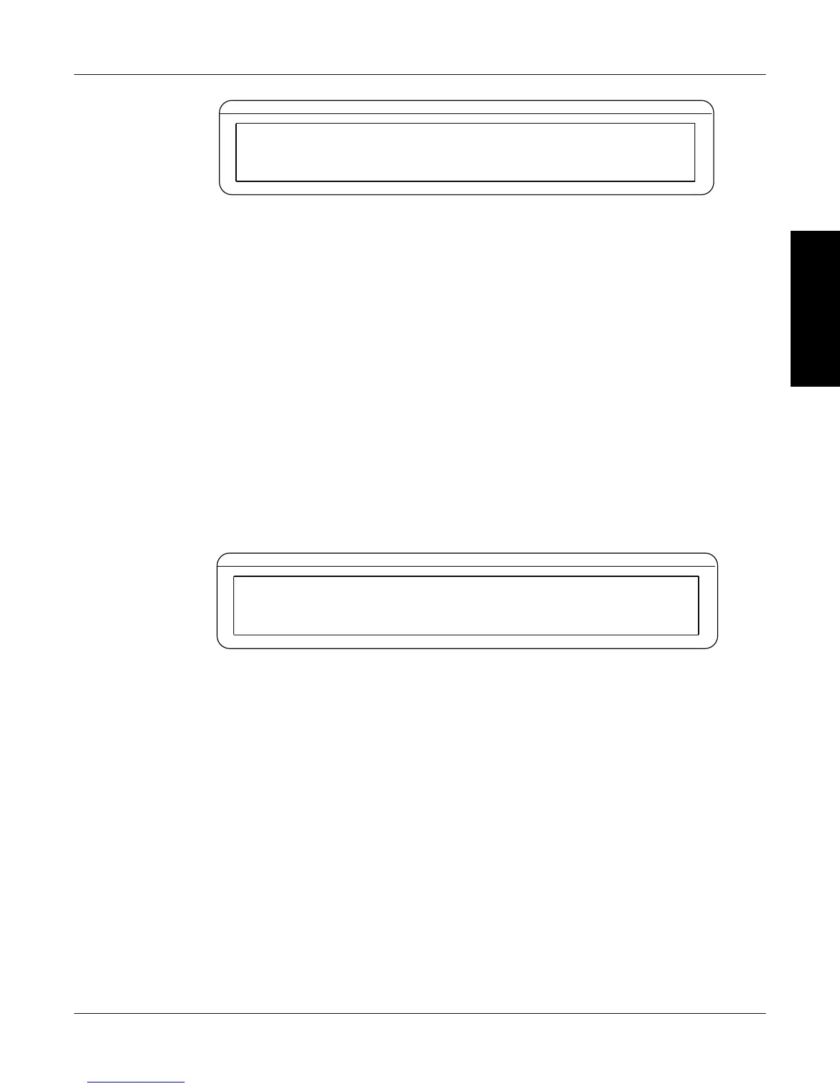
Figure 3–28 Encoder Menu
5. Press POWER UNITS button until the desired source selection for the TSC is reached (TACH
A, QUAD DEG, AI 1).
3.4.1 TaCH a
1. From the main menu follow the instrumentation setup instructions. See Section 3.4 -
Instrumentation Setup (Speed) and Figure 3–28 Encoder Menu.
2. Press TORQUE UNITS button and use and buttons and Decrease/Increase dial to set
the PPR.
3. Press SCALE P button and use and buttons and Decrease/Increase dial to set the Speed
Alarm.
4. Press SHIFT 3 times to complete the setup and return to the main menu.
3.4.2 quaD Deg
1. From the main menu follow the instrumentation setup instructions. See Section 3.4 -
Instrumentation Setup (Speed). The display should appear as follows:
BRAKE STATUS SET POINT SET POINT PID
TORQUE SPEED USER DISPLAY
SOURCE
QUAD DEG
PPR
XX
SPEED ALARM
XXXX
ANGLE
XX
Figure 3–29 QUAD DEG Menu
2. Press TORQUE UNITS button and use and buttons and Decrease/Increase dial to set
the PPR.
3. Press MAX SPEED button and use and buttons and Decrease/Increase dial to set the
Angles.
4. Press SCALE P button and use and buttons and Decrease/Increase dial to set the Speed
Alarm.
5. Press SHIFT 3 times to complete the setup and return to the main menu.
3.4.3 ai 1
1. From the main menu follow the instrumentation setup instructions. See Section 3.4 -
Instrumentation Setup (Speed). The display should appear as follows:

 Loading...