19
SETUP
3. Installation/Configuration
Note: Before installing the DSP7000, you should become familiar with
the front and rear panels, as outlined in Chapter 2–Controls.
3.1 POWERING UP THE DSP7000
WARNING! TO REDUCE THE RISK OF ELECTRIC SHOCK, MAKE
SURE THE DSP7000 IS EARTH GROUNDED BEFORE
STARTING!
3.1.1
Self-TeST
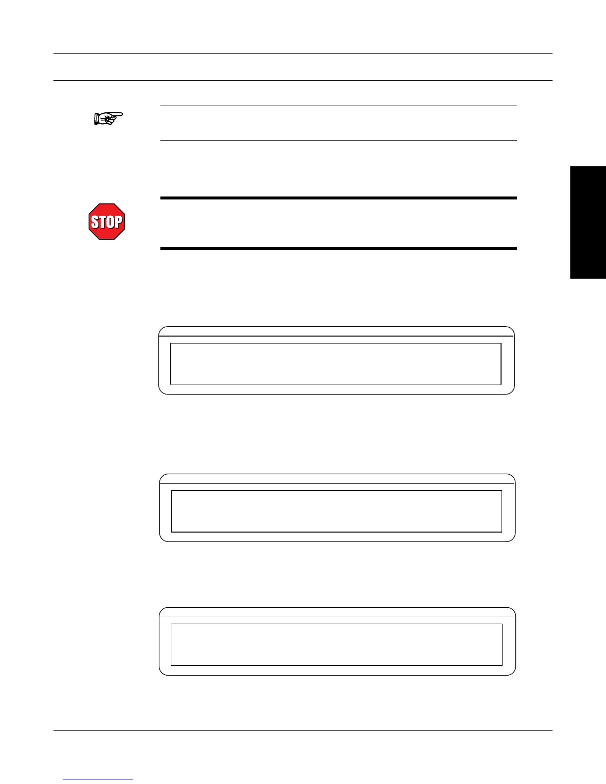
After turning the power on to the DSP7000, the display panel will show the message “SERIAL KEY
PAD REV X.X” while the DSP7000 is downloading the program.
BRAKE STATUS SET POINT SET POINT PID
TORQUE SPEED USER DISPLAY
SERIAL KEY PAD REV X.X
Figure 3–1 Program Download Display
When the program download is complete, the message “MAGTROL MODEL DSP700X, FW
REV:XX, FPGA REV:XX” appears.
BRAKE STATUS SET POINT SET POINT PID
TORQUE SPEED USER DISPLAY
MAGTROL
MODEL DSP700X
FW REV:XX
FPGA REV:XX
Figure 3–2 Revision Display
If the alarms are disabled, the following display message will appear at this time.
BRAKE STATUS SET POINT SET POINT PID
TORQUE SPEED USER DISPLAY
WARNING ALL ALARMS ARE DISABLED
ON TSCX
Figure 3-3 Alarm Warning Display
To activate the alarms, refer to Chapter 6 - Alarm System.

 Loading...