97
Magtrol Model DSP7000 Dynamometer Controller
Chapter 8 – Optional Equipment
operation
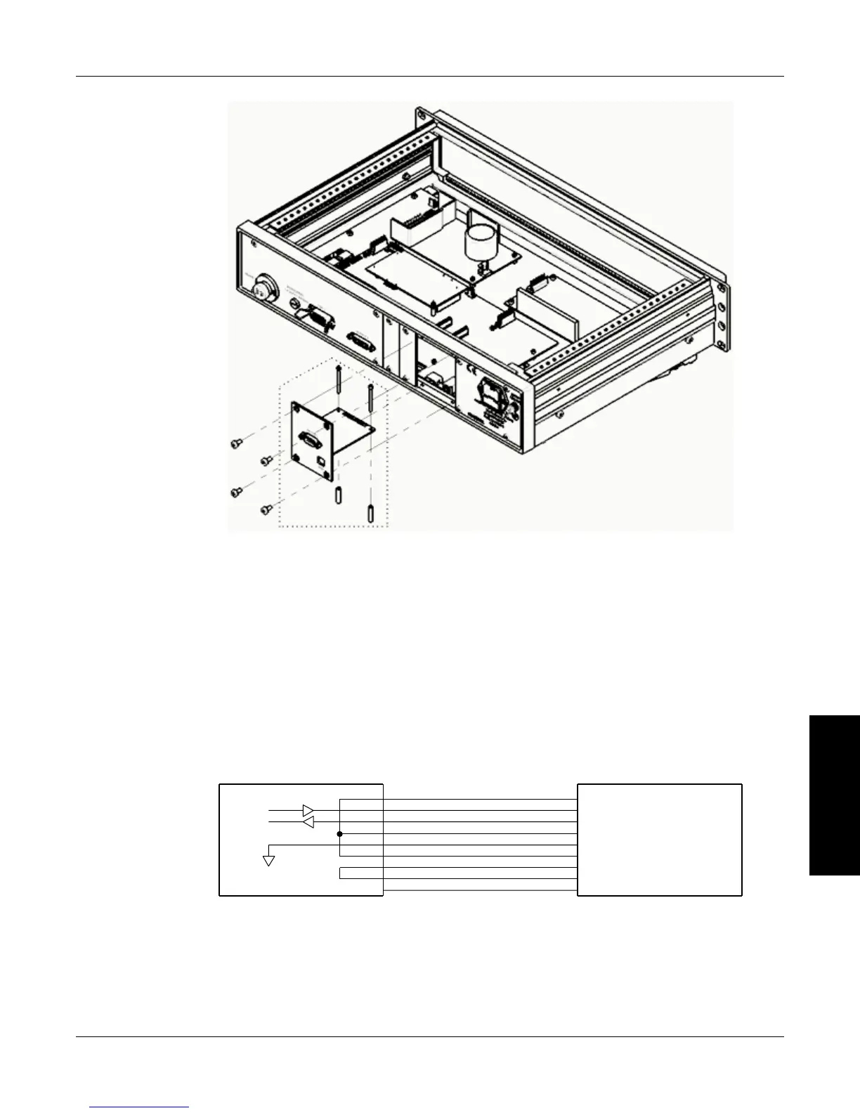
Figure 8–14 RS-232 Card Installation
4. Mount the two standoffs and the two socket head cap screws onto the main board. Use four
Philips pan head screws to secure the RS-232 card into the rear panel of the DSP7000.
5. Replace the top cover of the DSP7000 and secure with four Philips pan head screws.
8.3.2 ConneCTion
The RS-232 connection includes null modem wiring internal to the unit. To install, use a straight
through pin-to-pin connector cable, which can be purchased from your local electronics store.
DIGITAL GROUND
4.
2.
3.
6.
1.
5.
7.
8.
9.
5. GND (SIGNAL GROUND)
1. DCD (DATA CARRIER DETECT)
6. DSR (DATA SET READY)
3. TX (TRANSMIT DATA)
2. RX (RECEIVE DATA)
4. DTR (DATA TERMINAL READY)
9. RI (RING INDICATOR)
8. CTS (CLEAR TO SEND)
7. RTS (REQUEST TO SEND)
TX
RX
N/C
GND
Figure 8–15 Straight Through Pin-to-Pin Cable Connection
 Loading...