114
Magtrol Model DSP7000 Dynamometer ControllerChapter 10 – Theory
MAINTENANCE
10.3 FILTER PARAMETERS
The Digital Filters of the DSP7000 are used to remove undesired noise from the TSC inputs. This
noise could be conducted from an undesired measured signal such as mechanical vibration or other
electrical sources.
The input to the A/D converter internal to the DSP7000 has a traditional analog filter that is comprised
of the following characteristics:
• -3dbPoint:3.8KHz
• A/DSampleRate:7812.5Hz
• 16AcquiredandAveragedSamples:Averageappliedtolteratarateof488.28125Hz
• FilterCutoffFrequencies:3Hz,10Hz,25Hz,50Hz
• FilterOutput:EquivalenttosecondorderButterworthanaloglter
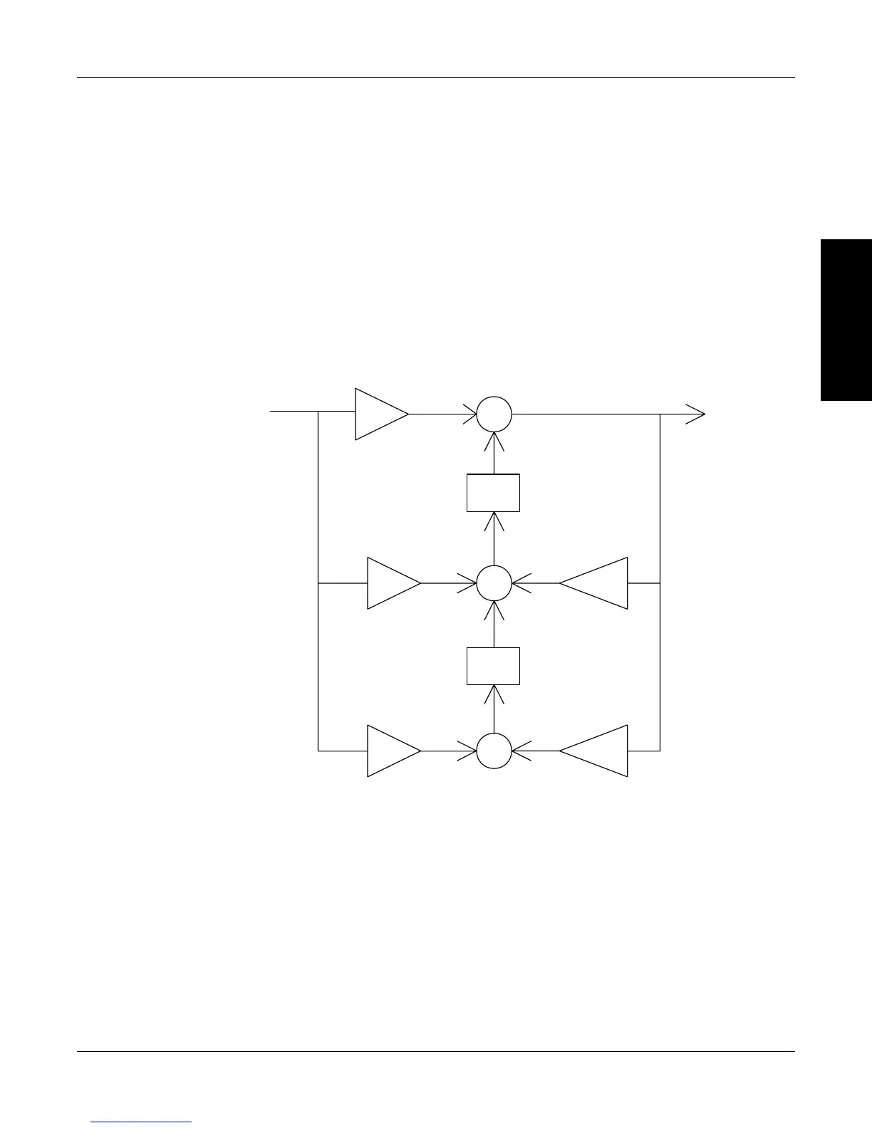
• TransposedDirectFormIIArchitecture:Thediagrambelowshowsthisarchitecture.
Z
-1
+
Z
-1
+
-a
1
b
0
+
b
1
b
2
-a
2
x(n) y(n)
w1
w2
Transposed Direct Form II
Figure 10–2 Transposed Direct Form II Architecture
With a Digital Filter, the DSP7000 is able to solve the following equations:
y(n) = b
0
* x(n) + w1
w1 = b
1
* x(n) + a1 * y(n) + w2
w1 = b
2
* x(n) + a2 * y(n)
The equations are applicable to each channel, occurring every 2.48 milliseconds.
 Loading...