95
Magtrol Model DSP7000 Dynamometer Controller
Chapter 8 – Optional Equipment
operation
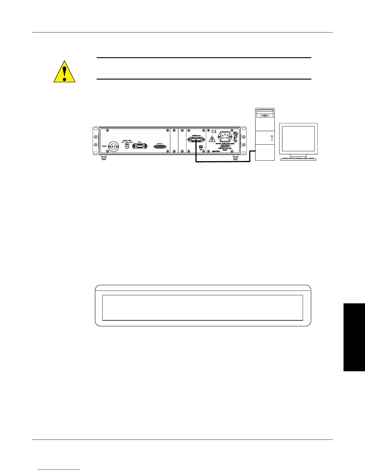
8.2.3 inSTalling THe gpiB (ieee-488) ConneCTor CaBle
Caution: make sure both the Computer and dsp7000 are turned off
before installing the gpib ConneCtor Cable.
1. Connect one end of a high-quality, double-shielded cable to the DSP7000 GPIB port.
2. Connect the other end to the USB port in your PC
PC
M-TEST
GPIB
Figure 8–11 GPIB Installation
8.2.4 CHanging THe gpiB priMary aDDreSS
Each instrument serviced by the GPIB has its own Primary Address code, which enables the computer
to obtain readings from the instrument. The factory default of the setting on the DSP7000 is 09.
Some PC interfaces can access from one to fifteen 4-bit primary addresses. Other interfaces can
access as many as thirty-one 5-bit primary addresses. The DSP7000 uses the 4-bit format. For
setup, follow the steps below.
1. Press the SHIFT button.
2. Press the SETUP button.
3. Press SCALE P button to select system. The display should appear as follows:
POWER
BRAKE STATUS SET POINTSET POINTPID
TORQUE SPEED USER DISPLAY
CONTR
GPIB ADDR RS232
MODE
XX
XXXXXX XXXX
Figure 8–12 Setup Menu Display
4. Press TORQUE UNITS until the desired primary address is reached (range 0-15).
5. Press SHIFT 2 times to exit and return to main menu.

 Loading...