119
Magtrol Model DSP7000 Dynamometer Controller
Appendix B: Front Panel/Display Menu Flow Charts
APPENDICES
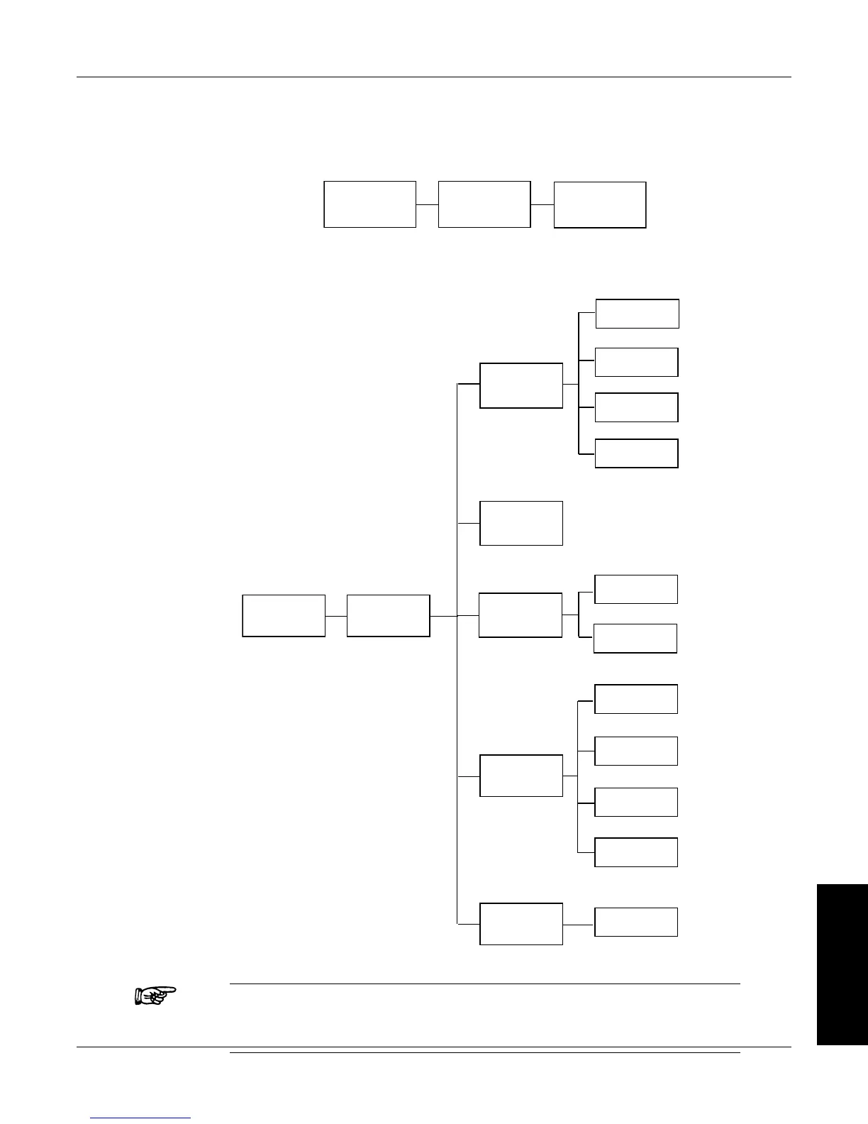
The following flow charts are a reference for navigating through the key functions of the DSP7000 Dynamometer
Controller. For step-by-step setup instructions, refer to the corresponding chapters in this manual.
B.1 PRIMARY KEY FUNCTIONS
ON
OFF
BRAKE
ON/OFF
TORQUE
SET
0.000–
99,999
4.
P 0–99%
6.
I 0–99%
7.
D 0–99%
8.
SPEED
SET
0.000–
99,999
5.
3.
OPEN
LOOP
ON
OFF
.2
TSC
TSC1
TSC2
.1
B.2 SECONDARY KEY FUNCTIONS
B.2.1 DiSplay BoTH
DISPLAY
BOTH
SHIFT
TSC1 & TSC2
B.2.2 SeTup
AUTOTUNE
SHIFT
SETUP
DYNO
MAXPOWER
ALARMS
DYNAMOMETER
ENCODERS
I/O
CHANNEL 1
CHANNEL 2
SYSTEM
CONTR
GPIB ADDR
RS232
MODE
USER
DISPLAY
Note: Refer to the flow charts on the following pages for a more detailed
breakdown of Dyno, Autotune, I/O, System and User. All flow
charts will be a continuation of B.2.2 beginning at SHIFT*.

 Loading...