16
Magtrol Model DSP7000 Dynamometer ControllerChapter 2 – Controls
GENERAL
INFORMATION
TSC1/TSC2 Connect torque signal cable here.
1. FLOW/CLUTCH
2. TACH. B
3. +24 VDC
4. +24 VDC COM
5. -24 VDC COM
6. -24 VDC
7. +5.0 VDC
8. +5.0 VDC COM
9. D.P. A
10. TACH. A
11. NC
12. D.P. B
13. TORQUE COMMON
14. TORQUE SIGNAL
Figure 2–7 TSC1/TSC2 Connector
SUPPLY 1/SUPPLY 2 Connect WB/PB DES supply for TSC1/TSC2 here.
1. SHIELD (EARTH)
2. ELECTRICAL ALARM
3. SUPPLY 1-N/C / SUPPLY 2-CLUTCH
4. SUPPLY +24VDC
5. N/C
6. +24 VDC COM
7. CURRENT SET POINT (SIGNAL)
8. WATER FLOW ALARM
9. N/C
10. TEMPERATURE ALARM
11. STAND-BY
12. N/C
13. +24 VDC COM
14. CURRENT SET POINT (ANALOG OV)
15. N/C
Figure 2–8 Supply 1/Supply 2 Connector
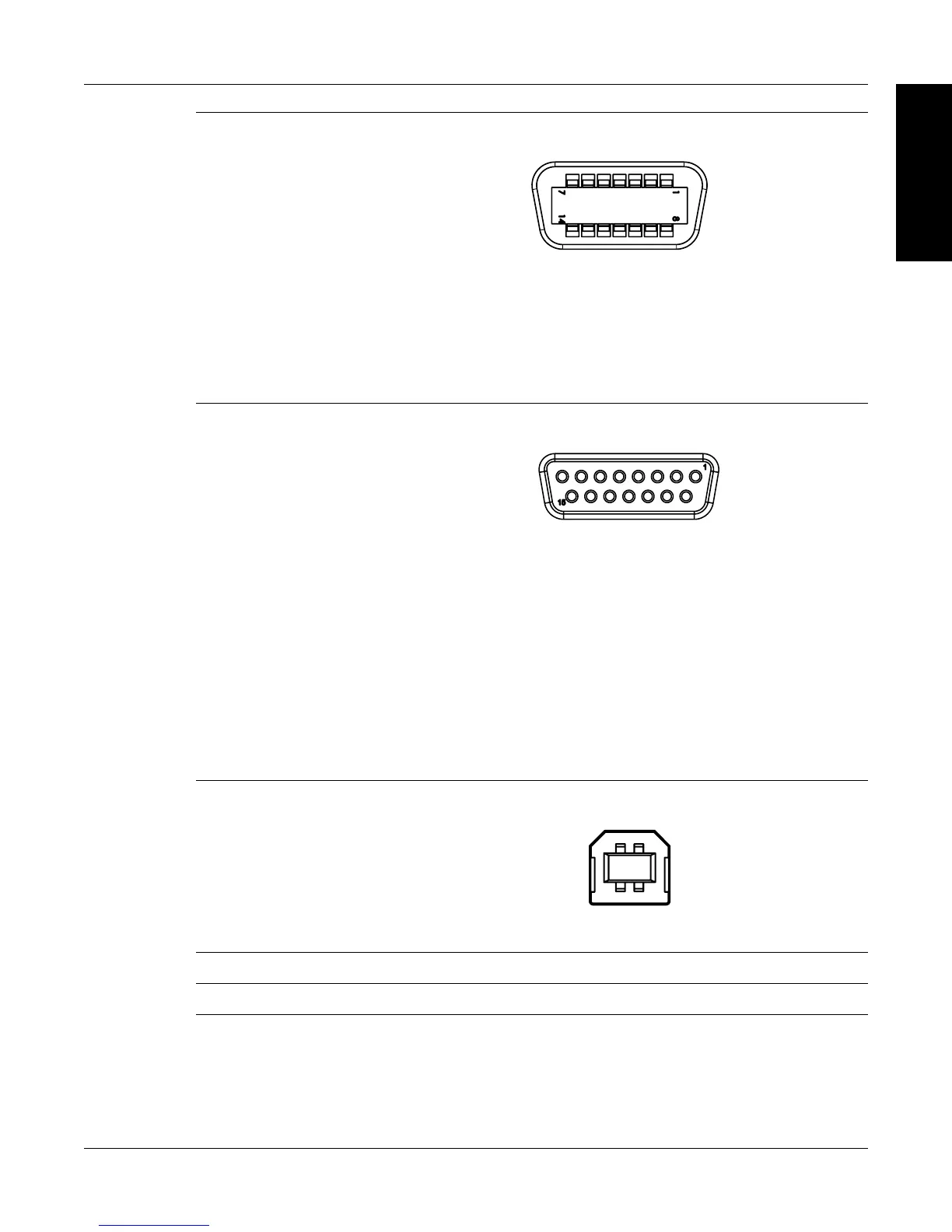
USB Connect PC USB cable here.
Figure 2–9 USB Connector
POWER Attach power cord here.
EARTH GROUND Attach earth ground here.

 Loading...