HYDRAULIC SYSTEM 16000 SERVICE/MAINTENANCE MANUAL
2-32
Published 05-09-17, Control # 014-28
If you think that a low pressure accessory system is not
operating properly, proceed as follows:
1. Install an accurate 0 to 1,000 psi (0 to 69 bar) hydraulic
pressure gauge between end of supply line and
corresponding port of actuator (brake port, for example).
Fittings are 06 ORS.
2. Release brake by slowly moving control handle in either
direction to operate corresponding function — pressure
should be 400 to 500 psi (28 to 35 bar).
3. Apply brake by moving control handle to off — pressure
should be zero.
4. If pressure is above 500 psi (35 bar), proceed as follows:
a. Loosen lock nut (2).
b. Adjust adjusting screw (3).
- Turn IN to INCREASE pressure
- Turn OUT to DECREASE pressure
c. Start and run engine at high idle.
d. Fully RETRACT (stall) a rotating bed jack with
switch on setup remote control only long enough to
get a gauge reading.
e. Repeat steps until gauge reads no higher than 500
psi (35 bar).
f. Hold adjusting screw in position and securely
tighten locknut.
5. Stop engine, remove gauge, and reconnect hydraulic
lines.
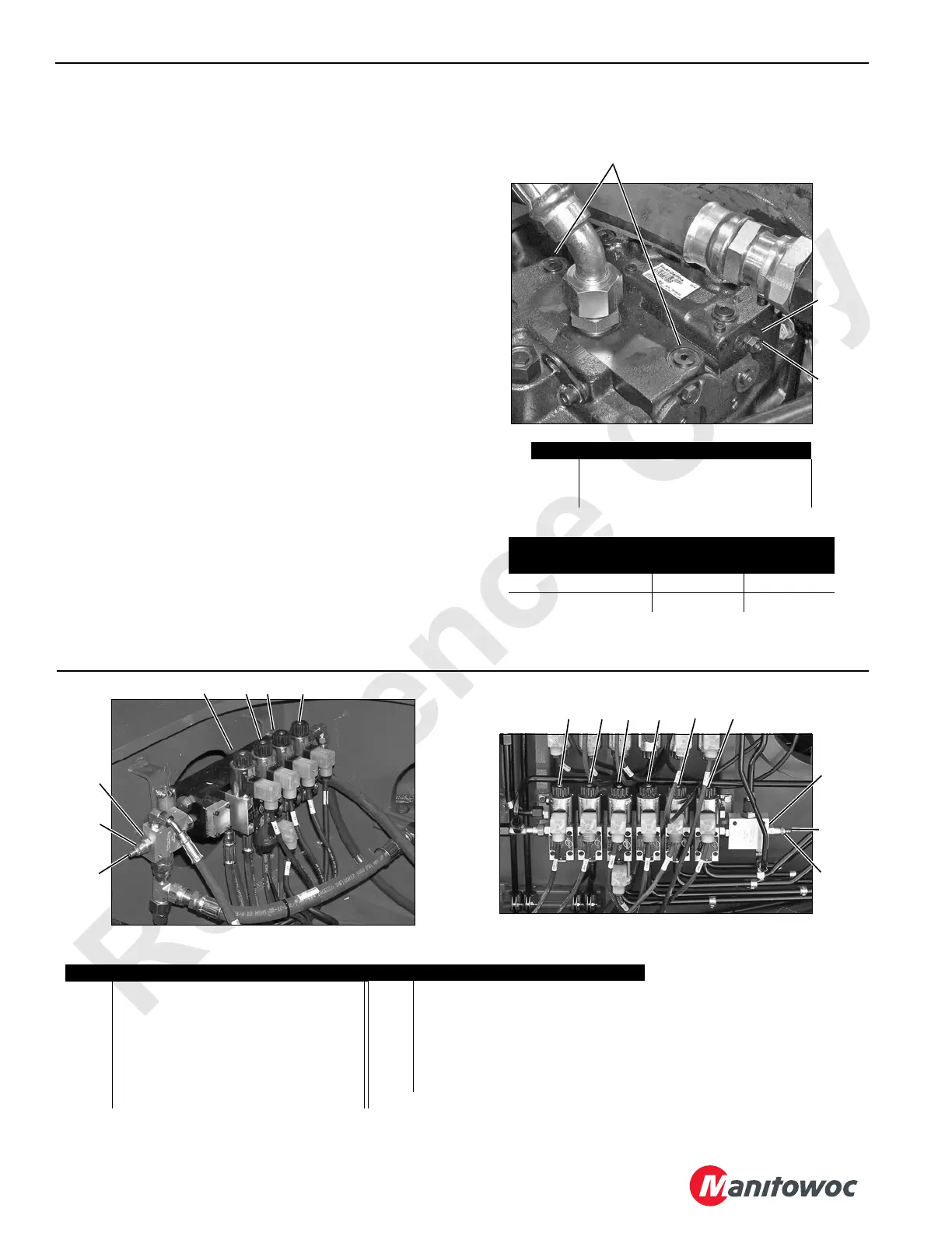
1
2
Item Description
1 Servo Gauge Ports (SAE 06)
2 Lock Nut
3 Adjusting Screw
Wrench Size
Pump Series
Lock Nut
Hex Size
Internal
Hex Size
Early Series Units 17 mm 5 mm
Current Series Units 10 mm 3 mm
FIGURE 2-31
P1535a
Typical Pump Installation
3
4
P2300
1
5 6 7
3
2
Inside Adapter Frame
FIGURE 2-32
P2308
10
9
12
11
138
1
3
2
Left Side of Rotating Bed
Item Description Item Description
1 Pressure Reducing Valve 8 Drum 2 to Drum 1 Diverting Solenoid
2 Lock Nut – 0.562 inch Hex 9 Drum 1 to Drum 2 Diverting Solenoid
3 Adjusting Screw – 0.188 inch Internal Hex 10 Drum 4 Pawl Solenoid
4 Swing Brake Solenoid Valve 11 R Travel to Drum 4 Diverting Solenoid
5 Swing Lock Solenoid Valve (past
production)
12 L Travel to Drum 3 Diverting Solenoid
6 Travel Brake Solenoid Valve 13 Drum 4 to Drum 5 Diverting Solenoid
7 Travel 2-Speed Solenoid Valve
 Loading...


