Manitowoc Published 05-09-17, Control # 014-28 3-15
16000 SERVICE/MAINTENANCE MANUAL ELECTRIC SYSTEM
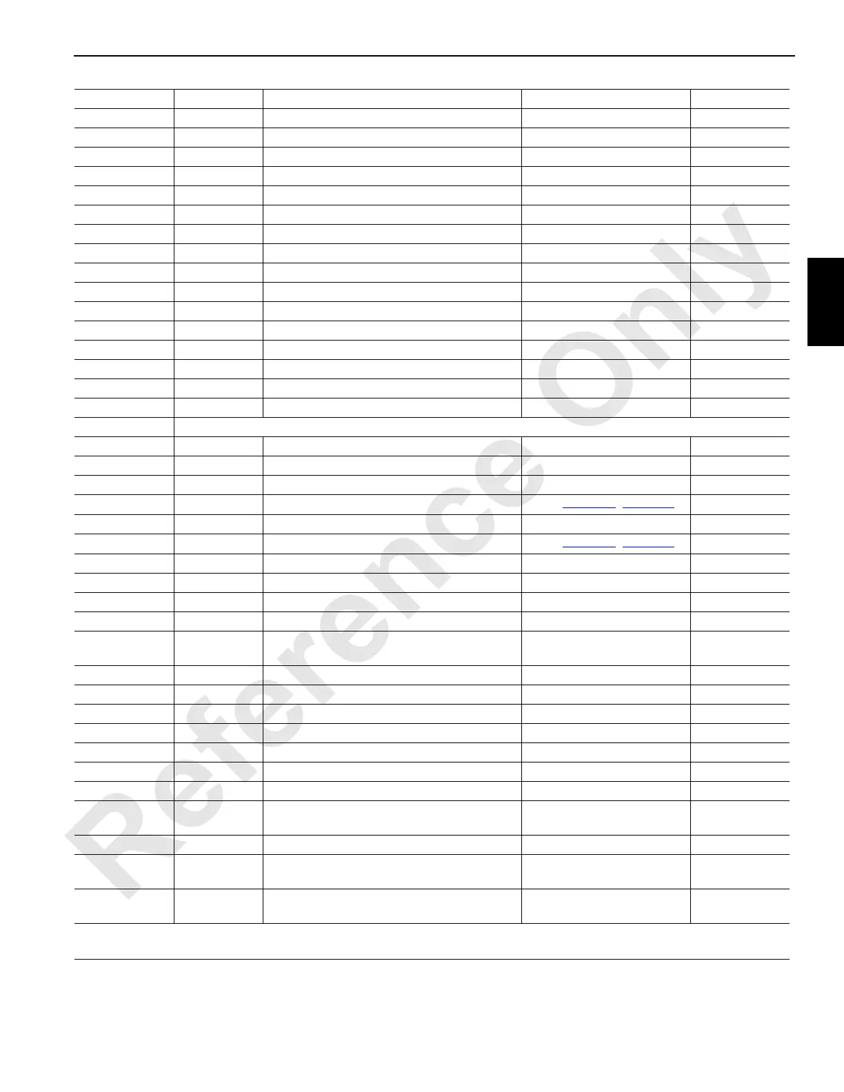
44-P DO-16 Left Rear Jack Solenoid - Retract 0 Volts Off; 24 Volts On CAN27-2-128
44-R DO-15 Left Rear Jack Solenoid - Extend 0 Volts Off; 24 Volts On CAN27-2-64
44-S DO-18 Right Rear Jack Solenoid - Retract 0 Volts Off; 24 Volts On CAN27-3-2
44-T Ground Rigging Winch Solenoid - Spool In Ground
44-U DO-19 Rigging Winch Solenoid - Spool In 0 Volts Off; 24 Volts On CAN27-3-4
44-V Ground Rigging Winch Solenoid - Spool Out Ground
44-W DO-20 Rigging Winch Solenoid - Spool Out 0 Volts Off; 24 Volts On CAN27-3-8
44-X Ground Mast Rasing Cylinders Solenoid - Extend Ground
44-Z DO-21 Mast Rasing Cylinders Solenoid - Extend 0 Volts Off; 24 Volts On CAN27-3-16
44-a Ground Mast Rasing Cylinders Solenoid - Retract Ground
44-b DO-22 Mast Rasing Cylinders Solenoid - Retract 0 Volts Off; 24 Volts On CAN27-3-32
44-c Ground Front Rotating Bed Pin Solenoid - Retract Ground
44-d DO-23 Front Rotating Bed Pin Solenoid - Retract 0 Volts Off; 24 Volts On CAN27-3-64
44-e Ground Front Rotating Bed Pin Solenoid - Extend Ground
44-f DO-24 Front Rotating Bed Pin Solenoid - Extend 0 Volts Off; 24 Volts On CAN27-3-128
44-g Ground Jumper to Node Select 4 Ground
44-k NS-3 Node Select 3 Jumper to Ground 0 Volts (With Jumper)
W46 Receptacle – Drum 4 and Pressure Sensors
46-A Ground Boom/Mast Hoist (Drum 4) Brake Solenoid Ground
46-B DO-7 Boom/Mast Hoist (Drum 4) Brake Solenoid 0 Volts Off; 24 Volts On CAN27-1-64
46-C Ground Boom/Mast Hoist (Drum 4) Left Side Motor Ground
46-D DO-8 Boom/Mast Hoist (Drum 4) Left Side Motor
See
Table 3-2, page 3-8
CAN27-1-128
46-E Ground Pump 7 Control (Accessory Pump) Ground
46-F DO-9 Pump 7 Control (Accessory Pump)
See
Table 3-2, page 3-8
CAN27-2-1
46-M NS-3 Node Select 3 Jumper to Ground 0 Volts (With Jumper)
46-R 24 Volts Boom/Mast Hoist (Drum 4) Speed Sensor 24 Volts Nominal
46-S 24 Volts Left Travel Reverse Pressure Sender 24 Volts Nominal
46-T 24 Volts Right Travel Forward Pressure Sender 24 Volts Nominal
46-U Ground
Left Travel Reverse Pressure Sender/
Jumper to Node Select 3
Ground
46-W Ground Right Travel Forward Pressure Sender Ground
46-Z Ground Left Travel Forward Pressure Sender Ground
46-a AI-9 Left Travel Reverse Pressure Sender 1 V at 0 psi; 5 V at 7,000 psi CAN14-2 *1
46-b AI-10 Right Travel Forward Pressure Sender 1 V at 0 psi; 5 V at 7,000 psi CAN14-4 *1
46-f AI-14 Left Travel Forward Pressure Sender 1 V at 0 psi; 5 V at 7,000 psi CAN15-4 *1
46-g 24 Volts Accessory Pressure Sender 24 Volts Nominal
46-h AI-15 Accessory Pressure Sender 1 V at 0 psi; 5 V at 7,000 psi CAN15-6 *1
46-j Ground
Boom/Mast Hoist (Drum 4) Speed Sensor/
Accessory System Pressure Sender
Ground
46-m 24 Volts Left Travel Forward Pressure Sender/ 24 Volts Nominal
46-r EC-2A Boom/Mast Hoist (Drum 4) Speed Sensor
1.2 or 3.2 Volts Not Moving;
2.2 Volts Moving
CAN48-4 *2
46-s EC-2B Boom/Mast Hoist (Drum 4) Speed Sensor
1.2 or 3.2 Volts Not Moving;
2.2 Volts Moving
CAN48-4 *2
*1 – Lower four bits can be multiplied by 5 or 10 depending on sender, then divided by 16 for an estimation of sender voltage.
*2 – Number in indicated bank should increment in positive direction and decrement in negative direction with item rotation.
 Loading...


