Grove Published 3-22-2021, Control # 702-02 4-39
GRT8120 OPERATOR MANUAL OPERATING PROCEDURES
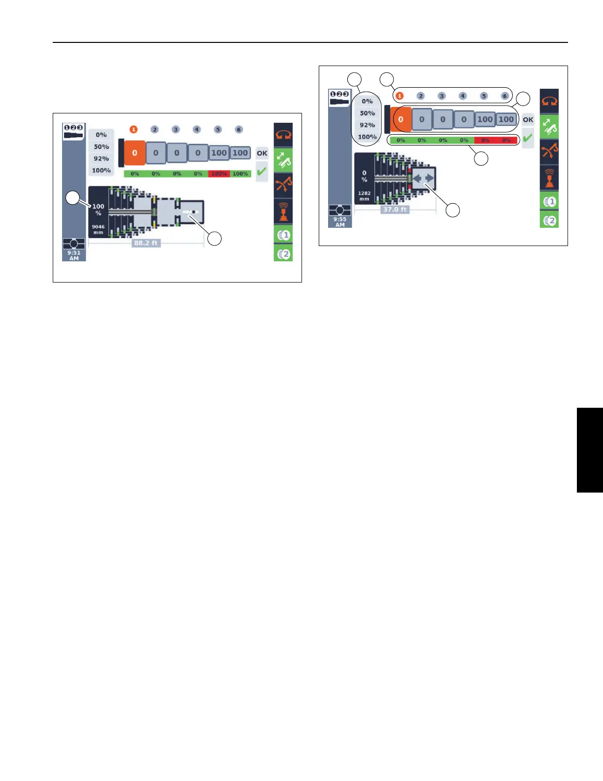
The end of the graphical representation of the rod at the T5
boom section which is at the 100% pinning location. The
slightly larger rectangular entity at the right end of the
telescoping cylinder rod represents the pinning mechanism.
The example in Figure 4-32 shows the value of 9046 mm for
the extension of the telescoping cylinder within the boom.
This is the value from the precision length sensor. The
example also shows a value of 88.2 ft as the overall boom
length. The example shows the T6 boom section had been
previously extended and locked at its 100% pinning location
and the T5 boom section is being pinned at the 100% pinning
location. The remaining boom sections are locked at their
0% pinning location.
As mentioned earlier, there are times when the crane control
system is performing automated motions. The example in
Figure 4-32 shows some moving dots (2) at the end of the
schematic graphic. These dots, as well as the one dark dot
cycling back and forth to the left and right, indicate that
automated motions are occurring.
Figure 4-33 shows the same screen when the operator is
able to control motions of the boom sections. In this case,
there is a left and/or right pointing arrow (1) (instead of the
dots shown in Figure 4-32). As is consistent with the
schematic's orientation, the left arrow indicates retracting the
boom, the right arrow indicates extending the boom. The
control device (typically the controller in the standard
controller option) would be moved to the left to retract the
boom, and it would be moved to the right to extend the boom
(while keeping in mind that only one boom section - the
boom section the telescoping cylinder is locked to - would be
moving).
The arrows (1, Figure 4-33), at some point in the telescoping
process, will flash. The flashing is an indication that an
unlocking or locking event will occur if the operator holds the
controller in the direction of that arrow for at least 1 second. If
this event begins, then the screen will change to the dots (as
described for Figure 4-32) so that the operator knows that an
automated motion or action is again occurring.
The RCL must be configured and activated in order to have
automated motions or to have operator control of the
telescoping function. If the Enter Rigging Mode screen on
the RCL display is used (accessed with the '?' icon on the
RCL display), then the telescoping action is paused. When
the check-mark is used on the RCL display to re-activate the
RCL, then the telescoping action resumes (whether
automated motion or operator control).
As seen in Figure 4-33, there are sets of numerical values at
the top portion of the screen above the graphical schematic
of the boom.
First, there is a set of values in a top row with values of 1 to 6
in circles (2, Figure 4-33). The 1 to 6 in the circles indicate
the telescoping boom sections (or “tele sections”). The 1 is
for the boom section that is the largest and closest to the
base section. This is referred to as T1. This then proceeds
from T2 to T6 for the 2 to 6 values.
The values under these boom section indication numbers
represent the requested final boom configuration (or “target
tele picture”). Figure 4-33 shows this set of values as
0-0-0-0-100-100 (3). This means that T5and T6 are to be
extended to its 100% pinning location, T2 is to be extended
to the 100% pinning location, and T1, T2, T3, and T4 are to
remain at the 0% pinning locations. It is vital that the operator
understand that this requested final boom configuration is
the first step in operating the pinned boom in the Semi-auto
Mode. Everything the control system performs with the
Semi-auto Mode is dependent on this requested final boom
configuration.
 Loading...


