OPERATING CONTROLS AND FEATURES GRT8120 OPERATOR MANUAL
3-40 Published 3-22-2021, Control # 702-02
CONTROLS AND FEATURES EXTERNAL TO
THE CAB
Counterweight Removal Control Pads
The Counterweight (2, Figure 3-20) is removed and installed
using hydraulic cylinders controlled by a counterweight
control panel located on each side of the superstructure. The
counterweight assembly is held in place by a hydraulic
cylinder and locking pins with pin clips.
There are two identical Counterweight Removal Control
Pads (1, Figure 3-20) located on each side of the
superstructure near the counterweight. Only one control pad
can be used at a time.
The following section provides a description of the LEDs and
buttons which makeup the Counterweight Removal Control
Pad. For complete procedures and precautions for how to
remove and install the counterweight, refer to Counterweight
Removal and Installation, page 5-66.
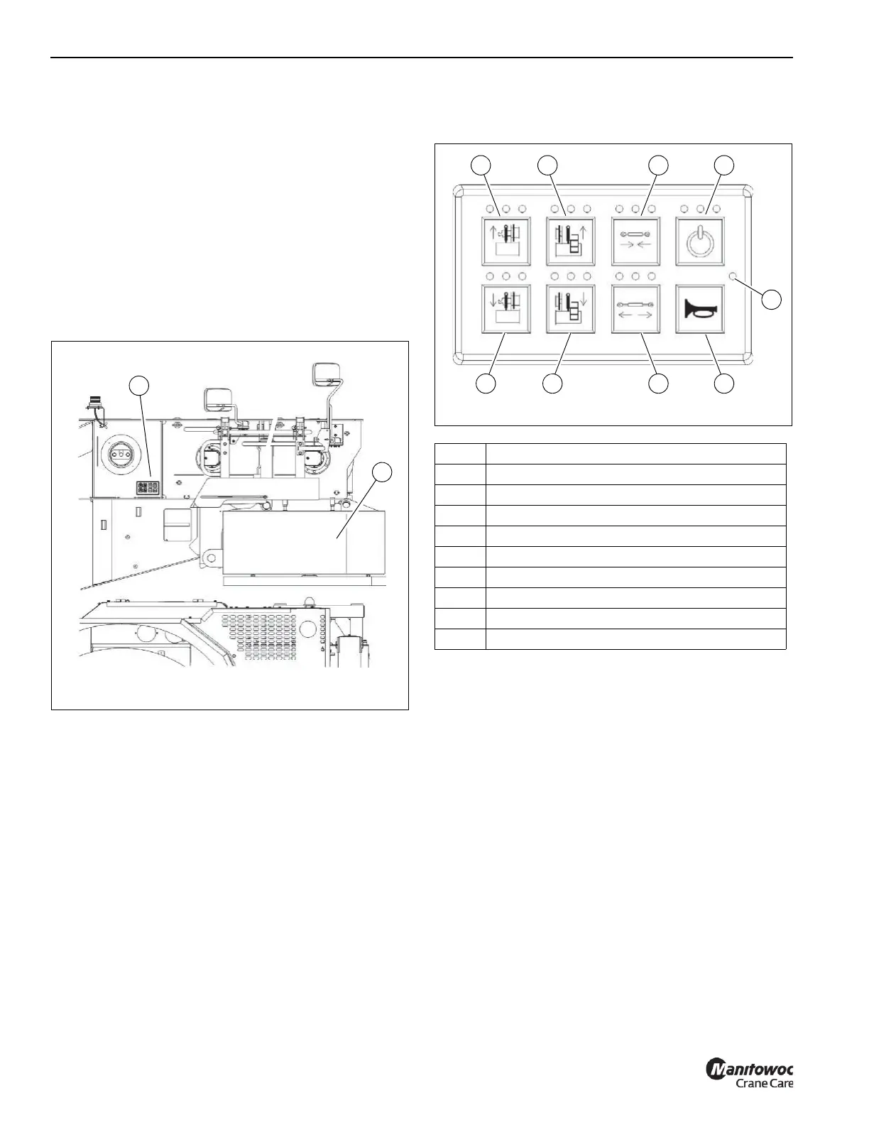
The Counterweight Removal Control Pads contain function
buttons and LED indicators.
Use the LED indicators to monitor power of the control panel
and performance of the counterweight removal system.
The Main Power LED (5, Figure 3-21) flashes green when
Main Power is on. Three other LED indicators, located above
each function button, indicate the status of the buttons.
• Green LED (left position) indicates function is enabled
• Yellow LED (middle position) indicates an error condition
• Red LED (right position) indicates the requested
function is not available or the counterweight removal
system is not enabled
The crane engine must be running with the parking brake in
the ON position, and no other crane functions enabled, for
the system to be fully operational.
Use the function buttons on the control pads to operate the
hydraulic cylinders of the counterweight removal system.
Right Counterweight Cylinder Raise Button
The Right Counterweight Cylinder Raise Button
(1, Figure 3-21) must be pushed and held to raise the right
cylinder holding the right side of the counterweight. The
operator must release the button when right side of the
cylinder is at desired position.
Left Counterweight Cylinder Raise Button
The Left Counterweight Cylinder Raise Button
(2, Figure 3-21) must be pushed and held to raise the left
cylinder holding the left side of the counterweight. The
operator must release the button when left side of the
cylinder is at desired position.
Item Description
1 Right Counterweight Cylinder Raise Button
2 Left Counterweight Cylinder Raise Button
3 Lock Cylinder Retract Button
4 Function Enable Button
5 Main Power LED Indicator
6 Horn Button
7 Lock Cylinder Extend Button
8 Left Counterweight Cylinder Lower Button
9 Right Counterweight Cylinder Lower Button
FIGURE 3-21
8658-2
1 2
4
3
9 8
6
7
5

 Loading...


