Grove Published 3-22-2021, Control # 702-02 5-25
GRT8120 OPERATOR MANUAL SET-UP AND INSTALLATION
Boom Extension Sensors
The front and rear boom extension mounting brackets
feature the following sensors:
• Rear Mounting Pin Sensor (3, Figure 5-27)—Sends a
signal to the crane control system when the rear boom
extension pin is extended in the rear boom extension
mounting bracket. The rear mounting pin is electrically
actuated from the ODM in the operator cab.
• Rear Side Sensor (4, Figure 5-27)—Sends a signal to
the crane control system when the boom extension fly
section is in the stowed position next to the boom base.
• Front Mounting Pin Sensor (7, Figure 5-27)—Sends a
signal to the crane control system when the front boom
extension pin is extended in the front boom extension
mounting bracket. The front mounting pin is electrically
actuated from the ODM in the operator cab. For more
information, see Boom Extension Pin Interlock
Mechanism, page 5-21.
• Front Side Sensor (8, Figure 5-27)—Sends a signal to
the crane control system when the boom extension base
section is against the front stowage bracket.
• Boom Nose Sensor (5, Figure 5-27)—Sends a signal to
the crane control system when the boom extension or
auxiliary boom nose is in the erected position.
Signals from the sensors appear in the ODM in the operator
cab to inform the operator about the status of the boom
extension.
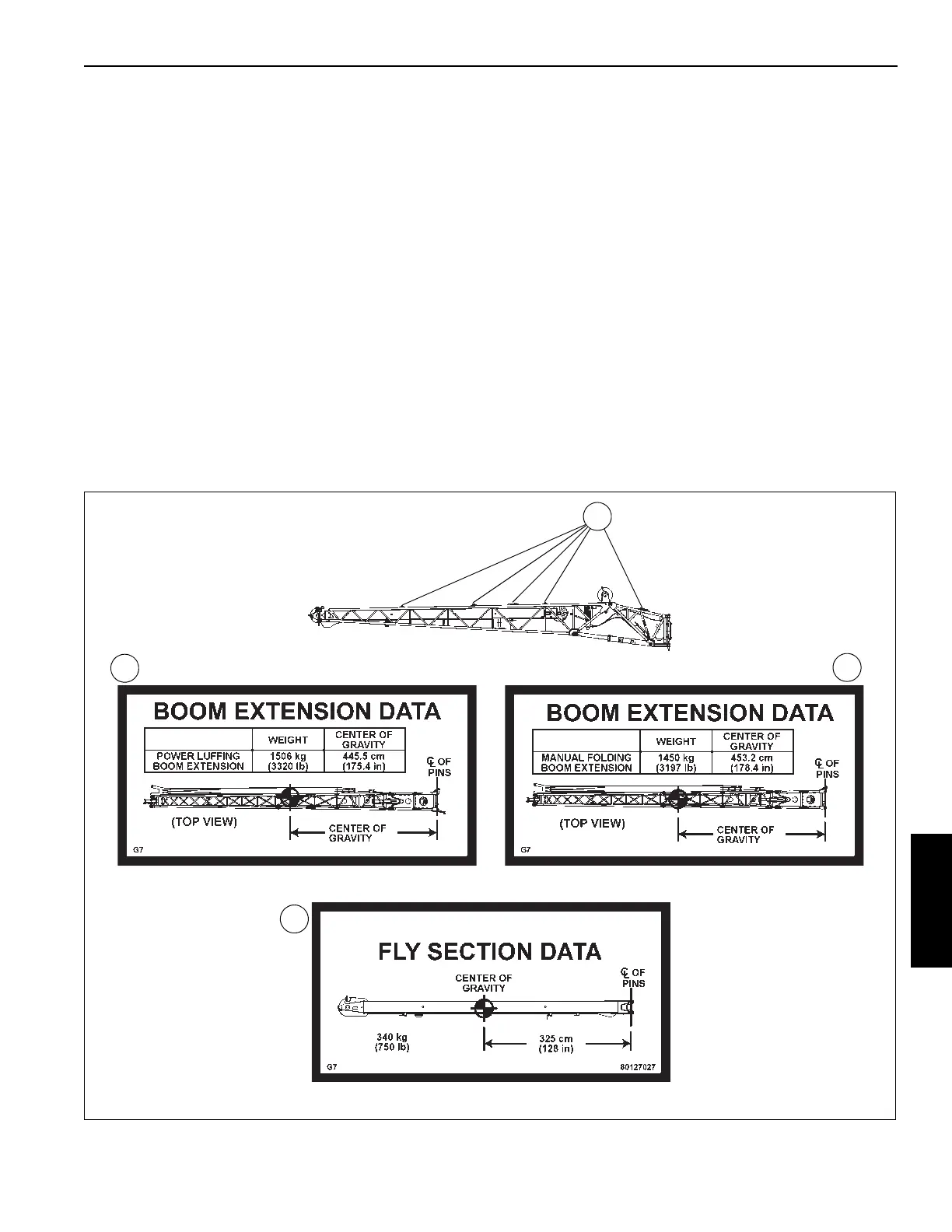
Lifting Points
The following section describes the sling attaching points for
lifting the boom extension.
The boom extension base section features five attaching
points on each side (10 total) (1, Figure 5-28). The
Transportation and Lifting decal (2) shows the center of
gravity information for the boom extension assembly and the
boom extension weight. Use the Transportation and Lifting
decal to determine which attaching points to use.
FIGURE 5-28
2
10089-2
1
Hydraulic Offset Boom Extension Assembly Mechanical Offset Boom Extension Assembly
Boom Extension Fly Section
2
2
 Loading...


