Grove Published 3-22-2021, Control # 702-02 4-27
GRT8120 OPERATOR MANUAL OPERATING PROCEDURES
Extending with the Main Boom Configuration
The CCS display shows various sectional views of the main
boom. To make you familiar with these representations more
quickly, the following section begins with an overview of the
telescoping mechanism and a telescoping process.
Overview
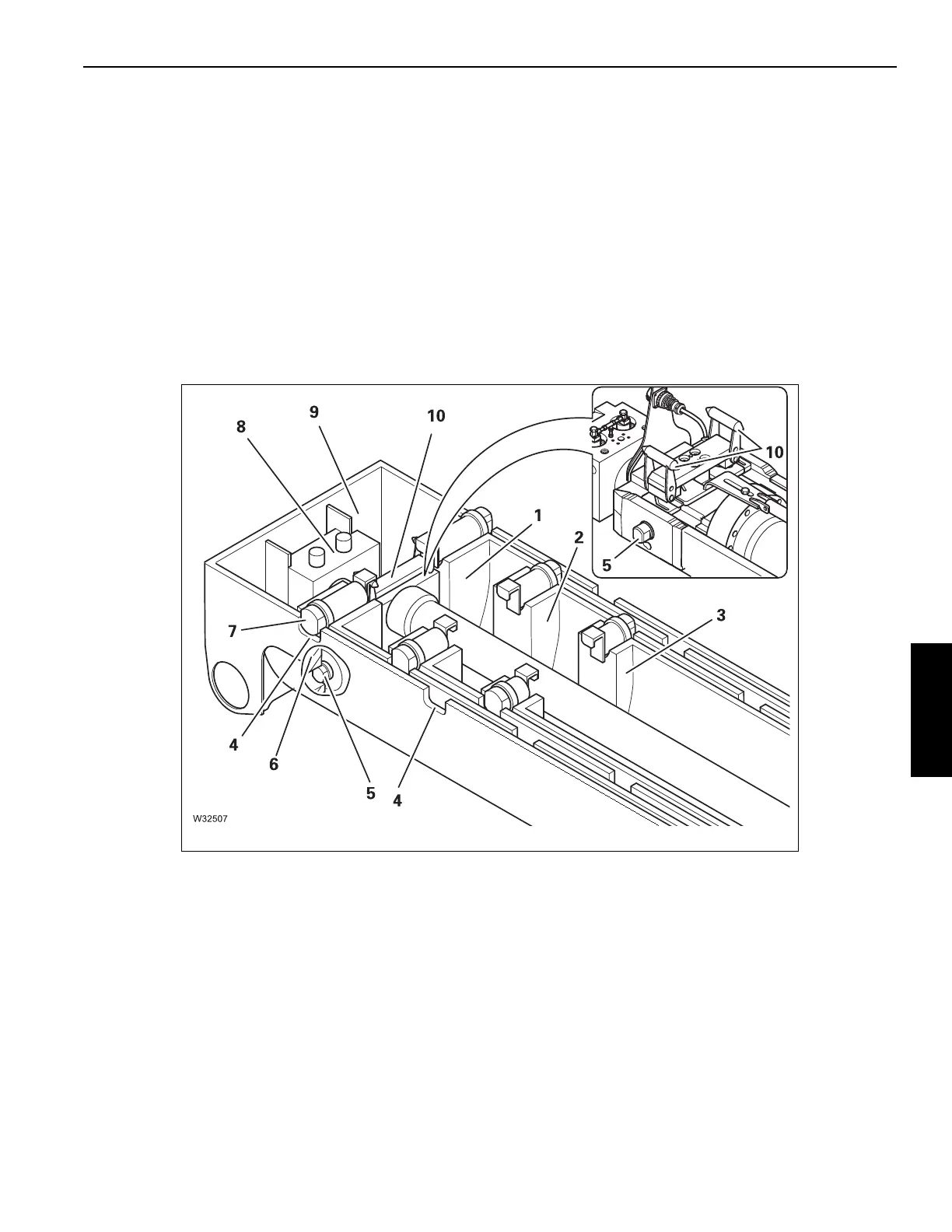
This illustration (Figure 4-5) shows the completely retracted
main boom with the base section (9) and the first three
telescopic sections I to III (1) to (3).Each telescopic section is
equipped with two section locking pins (7) which are
extended by spring force.
The section locking pins (7) are pushed into the cutouts (4) of
the telescopic section at the locking points – the telescopic
section is locked.
The telescoping cylinder is attached to the base section (9)
with the piston rod (8). The telescoping cylinder has two
cylinder locking pins (5) at the bottom and a mechanism at
the top (10).
When the telescoping cylinder is positioned at a locking
point:
The locking pins (5) can be extended into the cutouts (6) –
the telescoping cylinder is locked.
The mechanism (10) engages into the locking pins (7) and
can retract them – the telescopic section is unlocked.

 Loading...


