Grove Published 3-22-2021, Control # 702-02 5-41
GRT8120 OPERATOR MANUAL SET-UP AND INSTALLATION
end of the fly section. For more information, see
Anemometer/Boom Position Light (Optional), page 5-63.
9. Remove the tag line from the end of the fly section.
10. Reeve the hoist rope. For more information, see Hoist
Rope Reeving, page 5-13.
11. Remove the anti-two block switch from the auxiliary
boom nose. For more information, see Anti-Two Block
(A2B) Switch, page 5-10. Install the anti-two block switch
on the nose of the fly section. For more information, see
Anti-Two Block Switch on the Boom Extension, page
5-58.
Stowing the Fly Section
Use the following procedure to stow the fly section on the
boom extension base section.
NOTE: This procedure assumes the boom extension base
section and fly section are fully erected.
1. Remove the anti-two block switch from the end of the fly
section. For more information, see Anti-Two Block
Switch on the Boom Extension, page 5-58.
2. Unreeve the hoist rope from the fly section sheave
assembly and boom extension mast sheave
assemblies. For more information, see Reeving the
Hoist Rope, page 5-55
3. Install the anti-two block switch on the end of the boom
extension base section. For more information, see
Anti-Two Block Switch on the Boom Extension, page
5-58.
4. If installed, disconnect and remove wind speed indicator
and boom position light assembly from the end of the fly
section. For more information, see Anemometer/Boom
Position Light (Optional), page 5-63.
5. Attach a tag line to the end of the fly section. This tag line
will aid in swinging the fly section into position.
6. Remove the retaining clip and pin (3, Figure 5-60) that is
inserted in to the left side fittings (1, 2). Place the pin in
its holder on the boom extension base section and
secure with retaining clip.
7. Slightly raise and/or lower the boom to help control the
boom extension. Swing and stow the fly section on the
boom extension base section.
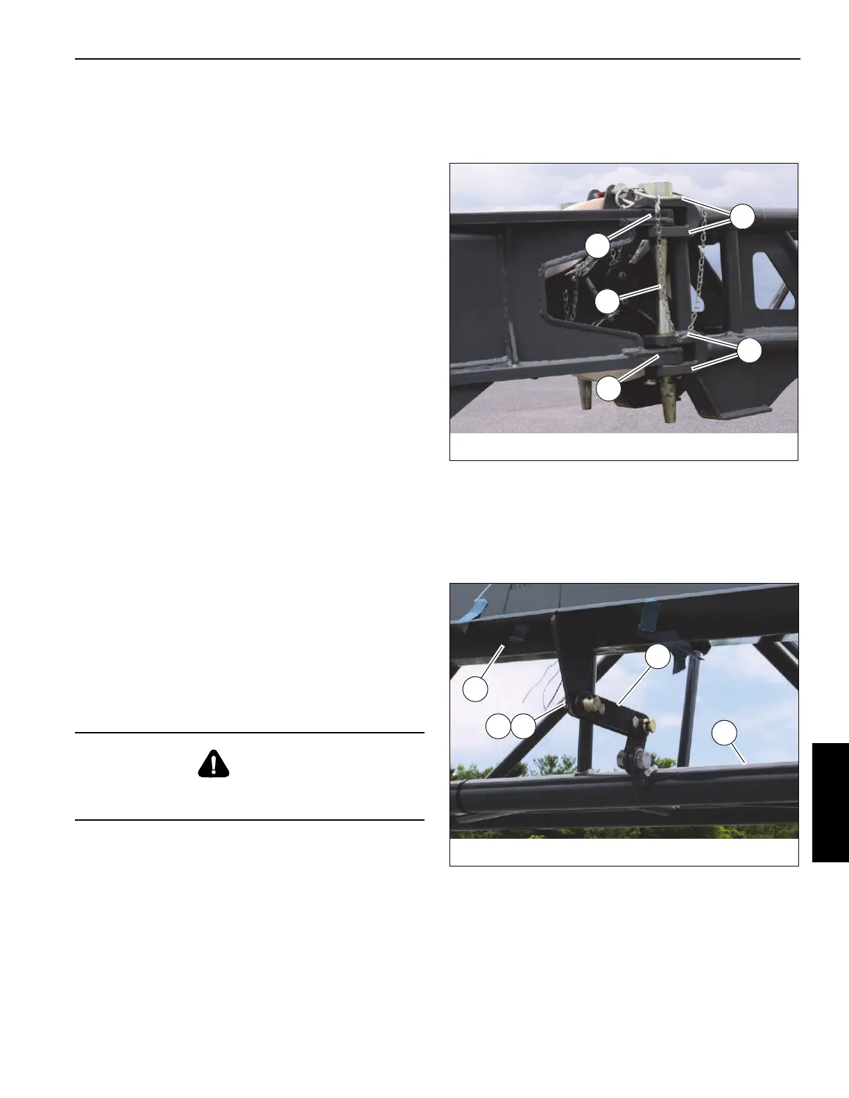
8. Attach the fly section (4, Figure 5-61) to the boom
extension base section (5) using the connecting link (1).
Secure connecting link with pin (3) and retaining clip (2).
DANGER
When stowing the fly section, make sure that all
personnel and equipment are kept clear of the swing path.
FIGURE 5-60
10088-14a
1
1
2
2
3
FIGURE 5-61
10088-11a
1
2 3
4
5

 Loading...


