OPERATING PROCEDURES GRT8120 OPERATOR MANUAL
4-44 Published 3-22-2021, Control # 702-02
is possible to command slight telescoping cylinder motions
to assist with locking or unlocking.
If telescoping function is still not operable, then the fault can
be assumed to be in the control system components, and
control system diagnostic procedures should be utilized.
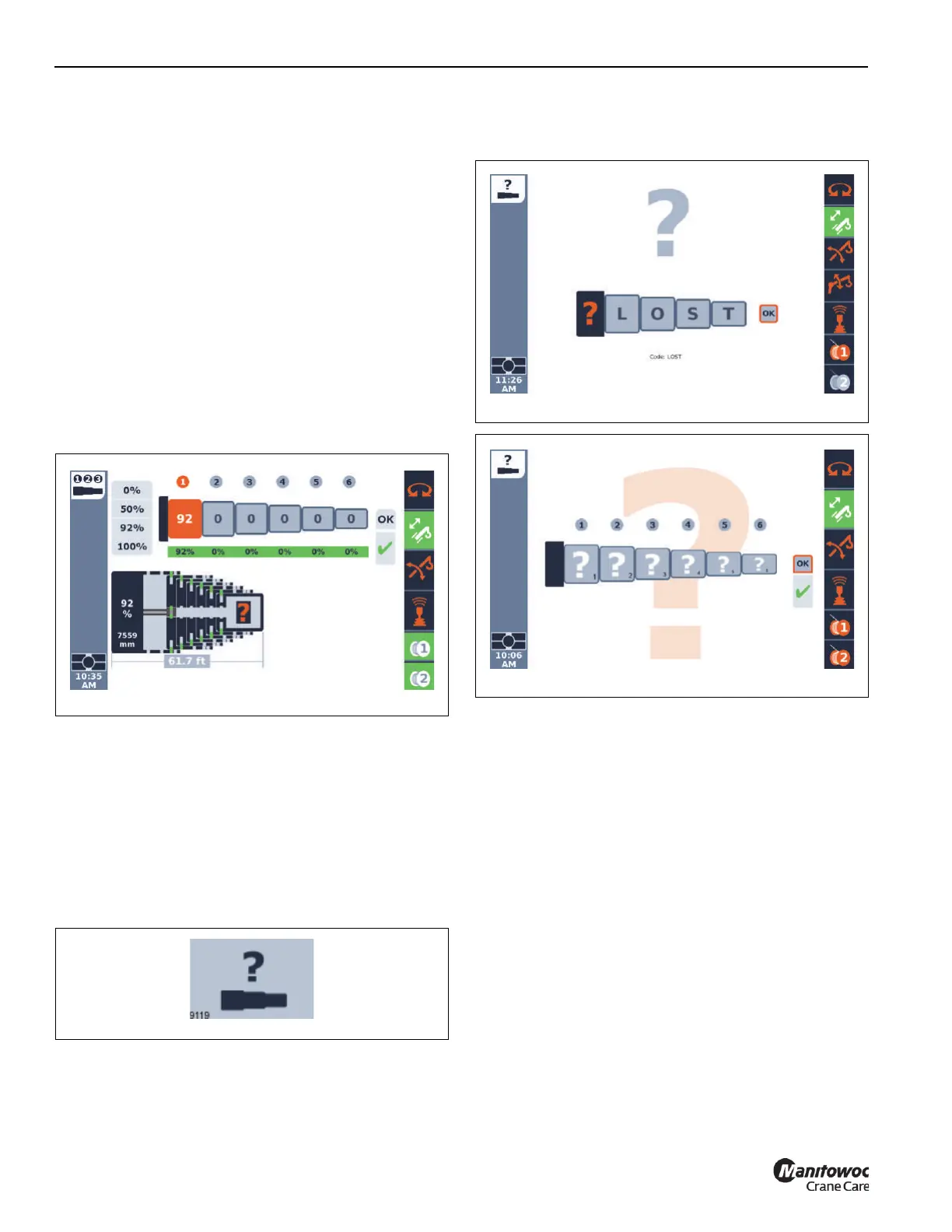
Semi-auto Mode Lost Boom Configuration
The Semi-auto Mode is expected to continuously monitor
and record the positions of the telescoping boom sections. If
this process is interrupted, perhaps by communication
interruption or repairing a component in the control system,
then this recorded boom configuration (or “tele picture”) may
be lost. The control system will not find components in the
expected position. When this occurs, a question mark icon
will appear in the screen as shown in Figure 4-42.
The operator can attempt to correct this condition by the
procedure in section Reset Telescoping Configuration, page
4-44.
Reset Telescoping Configuration
If the actual boom configuration (or “actual tele picture”) is no
longer considered valid by the control system (the question
mark icon appears in the Semi-auto screen), then the
following procedure can be used to reset (or “teach”) the
telescoping configuration:
• Enter the request reset telescoping screen on the
Operating Display Module (ODM). Figure 4-43 shows
the icon for this screen.
The request reset telescoping screen appears as shown in
Figure 4-44. This screen is for entering a confirmation code.
The confirmation code is L-O-S-T. When these letters are
entered on the screen, then an Enter button can be used on
the OK shown on the screen. If this is the correct code, then
the reset telescoping screen appears as shown in
Figure 4-45.
• In the reset telescoping screen, as shown in
Figure 4-45, the operator can indicate the current boom
configuration (“actual tele picture”). It is seen that there
are 6 available boxes (for the 6 telescoping boom
sections). Each of these spin boxes can be used to
change to one of the following:
- 0%
- 50%
- 92%
- 100%
- Unlock icon (appears when the 0% value is shown
and then the jog dial or operating display arrow
button is used to get a value below 0%).
• Each of the spin boxes needs to be set to a value or
indication of the current actual configuration of the
boom. If a boom section is locked at a 50% location,
then that boom section spin box is to be set to the 50%.
If a boom section is unlocked (and able to be operated
by the telescoping cylinder), then that boom section spin
box is to be set to the Unlock icon).

 Loading...


