OPERATING PROCEDURES GRT8120 OPERATOR MANUAL
4-116 Published 3-22-2021, Control # 702-02
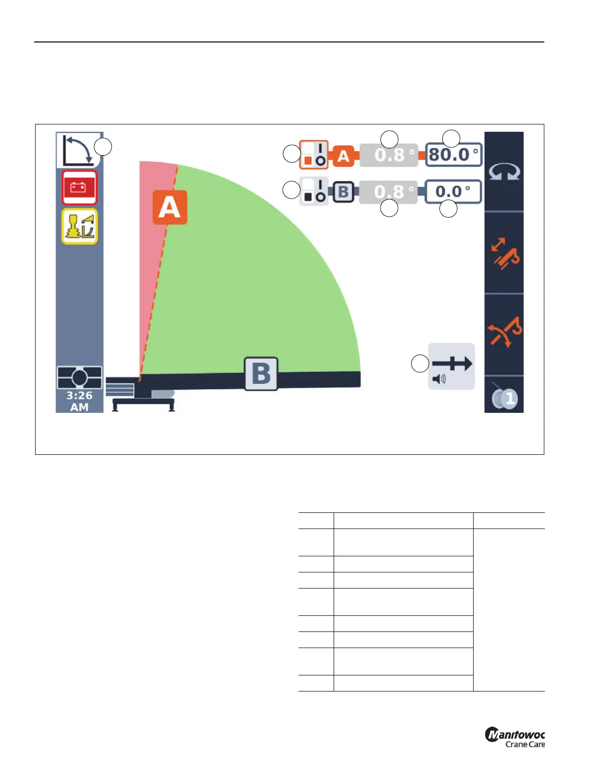
Boom Angle Limitation
If the Boom Angle Limitation Menu is selected from the Main
Menu of WRL Limitations (3, Figure 4-108), then the Boom
Angle Limitation Screen will be shown (Figure 4-110).
Using the Left Arrow and Right Arrow Function keys on the
Navigation Control Pad (4, Figure 4-62) or the Jog Dial
(5, Figure 4-63) changes the Icon highlighted on the screen.
As the arrow keys are pressed, the highlight will move
between the Icons, with the color orange typically meaning
that the Icon is selected and can be affected by subsequent
actions. In Figure 4-110, you will see that the highlighted Icon
in orange for the Enable/Disable Switch Symbol for the
maximum boom angle is selected since it has the orange
color highlighting. Table 4-9 lists the WRL Limitation Screen
Symbols.
NOTE: The Boom Angle can be “typed in” or set by a boom
position.
Setting the Boom Angle Limitation Menu
The Boom Angle Limitation Menu allows the operator to set
the upper and/or lower limits for the boom to operate within.
FIGURE 4-110
9841-10
Boom Angle Limitation Screen
Example Only - Display Values May Vary
2
5
3
6
4
7
8
1
Item Description Refer to
1
Upper A (Maximum Boom
Angle) Limit ON/OFF
Figure 4-110
2 Current Boom Angle
3 Maximum Boom Angle Limit
4
Lower B (Minimum Boom
Angle) Limit ON/OFF
5 Current Boom Angle
6 Minimum Boom Angle Limit
7
Audible Alert or Lock-out
Symbol
8 Boom Angle Limitation Icon

 Loading...


