5-56 Published 3-22-2021, Control # 702-02
SET-UP AND INSTALLATION GRT8120 OPERATOR MANUAL
Offsetting the Mechanical Boom Extension
The GRT8120 boom extension features manual offset or
hydraulic offset. The standard boom extension can be offset
manually to 0°, 20°, or 45°. The hydraulic boom extension
can be offset from 0° to 45° and controlled from the operator
cab.
Mechanical Extension Angle Adjusting Mechanism
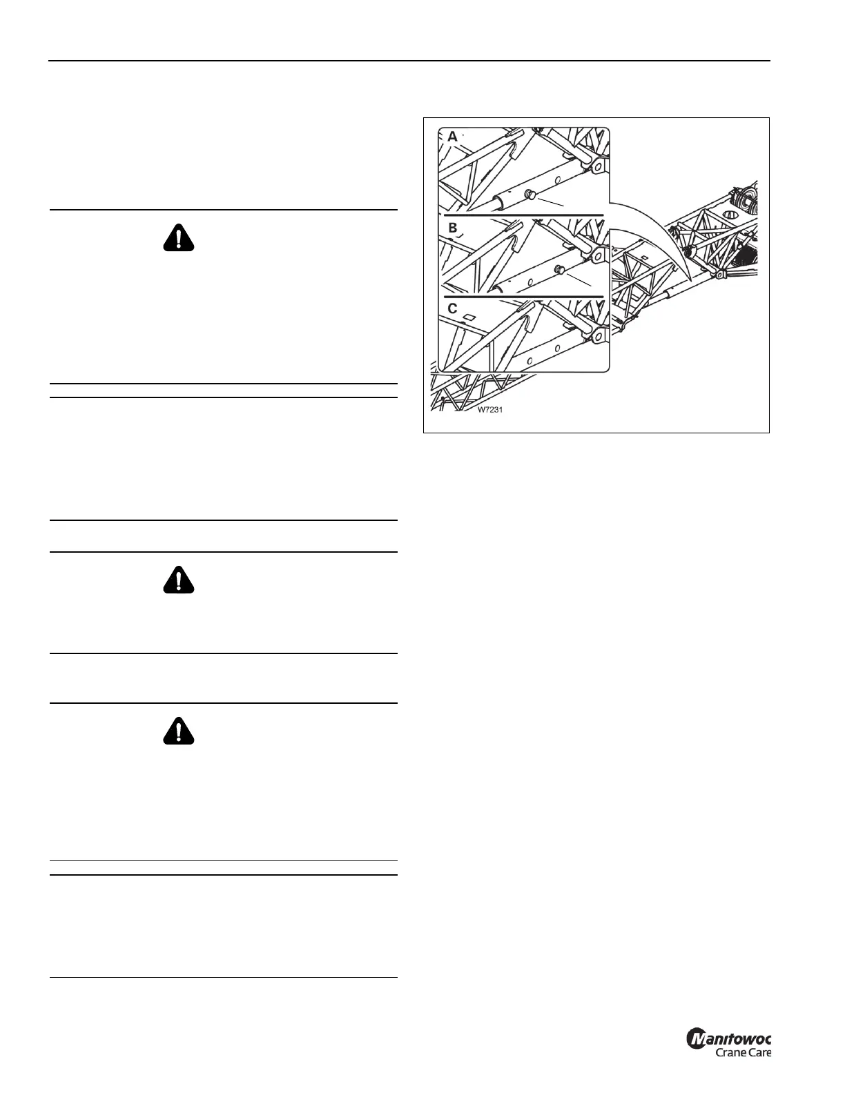
Refer to Figure 5-79.
The boom extension angle is determined by the position of
the adjusting pin. There are three positions:
•0° angle: (A) – For a 0° angle, the pin (1) is installed in
the front location and is secured with the retaining clip.
• 20° angle: (B) – For a 20° angle, the pin (1) is installed in
the rear location and is secured with the retaining clip.
• 45° angle: (C) – For a 45° angle, the pin (1) is removed
and stored in the operator cab.
Setting the Offset Angle with an Auxiliary Crane
NOTE: The information in this section only applies to the
mechanical luffing boom extension.
1. Lift the extension with the auxiliary crane until the pin
(1, Figure 5-79) is relieved of load.
2. Lift or lower the extension with the auxiliary crane until
the adjusting pin can be installed into the hole for the
required angle (refer to Figure 5-79).
3. Install the pin into the 0° or 20° offset hole, and then
secure with the retaining clip. If offset is to be 45°,
remove pin and store in the operator cab.
4. Lower the boom extension with the auxiliary crane and
remove the lifting gear.
When setting a 45° offset, if the boom extension now
touches the ground at the current angle, the angle will
set itself when the main boom is raised.
WARNING
Crushing Hazard!
Always secure the adjustable boom extension with an
auxiliary crane or set the nose of the extension on the
ground before you remove the adjusting pins when
adjusting the angle of the boom extension.
This prevents the extension from suddenly unfolding and
causing serious injury or death.
CAUTION
Risk of Equipment Damage!
Always stow the mast sheave assemblies before
adjusting the boom extension offset angle.
This will prevent any interference between the mast
sheave assemblies and boom extension.
DANGER
Crushing Hazard!
During installation and removal, always use the proper
equipment with sufficient load bearing capacities.
WARNING
Crushing Hazard!
Uncontrolled movement of the boom extension can result
in death or serious injury. The Boom extension must be
supported before removing the adjusting pins.
Support the extension with an assist crane or set the tip of
the extension on the ground before adjusting the angle.
CAUTION
Machine Damage!
The mast sheave must be stowed before adjusting the
offset angle of the extension. Failure to stow the deflection
sheave may result in damage to the extension or sheave.
W7231
FIGURE 5-79
1
1
- 45°
- 0°
- 20°

 Loading...


