5-22 Published 3-22-2021, Control # 702-02
SET-UP AND INSTALLATION GRT8120 OPERATOR MANUAL
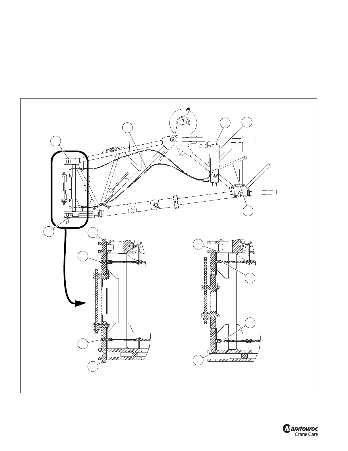
Front Mounting Pin Handle
The front mounting pin handle (5, Figure 5-26) moves in
unison with the front mounting pin (3), providing a visual cue
for operators outside of the operator cab to know the status
of the front boom extension mounting pin (3):
• Handle up—The front mounting pin (3) is extended in
the front mounting bracket and the boom nose
installation pins (4) are unlocked.
• Handle down—The front mounting pin (3) is retracted
and the installation pins (4) are locked.
The handle is also used to manually release the front boom
extension mounting pin interlock so that the boom extension
can be removed from the crane.
FIGURE 5-26
2
1
3
5
Installation Pins (4) Locked
Installation Pins (4) Unlocked
4
4
4
4
6
6
6
6
Front Mounting Pin (3) Unlocked
Front Mounting Pin (3) Locked
4
4
 Loading...


