Grove Published 3-22-2021, Control # 702-02 5-63
GRT8120 OPERATOR MANUAL SET-UP AND INSTALLATION
ANEMOMETER/BOOM POSITION LIGHT
(OPTIONAL)
Installing
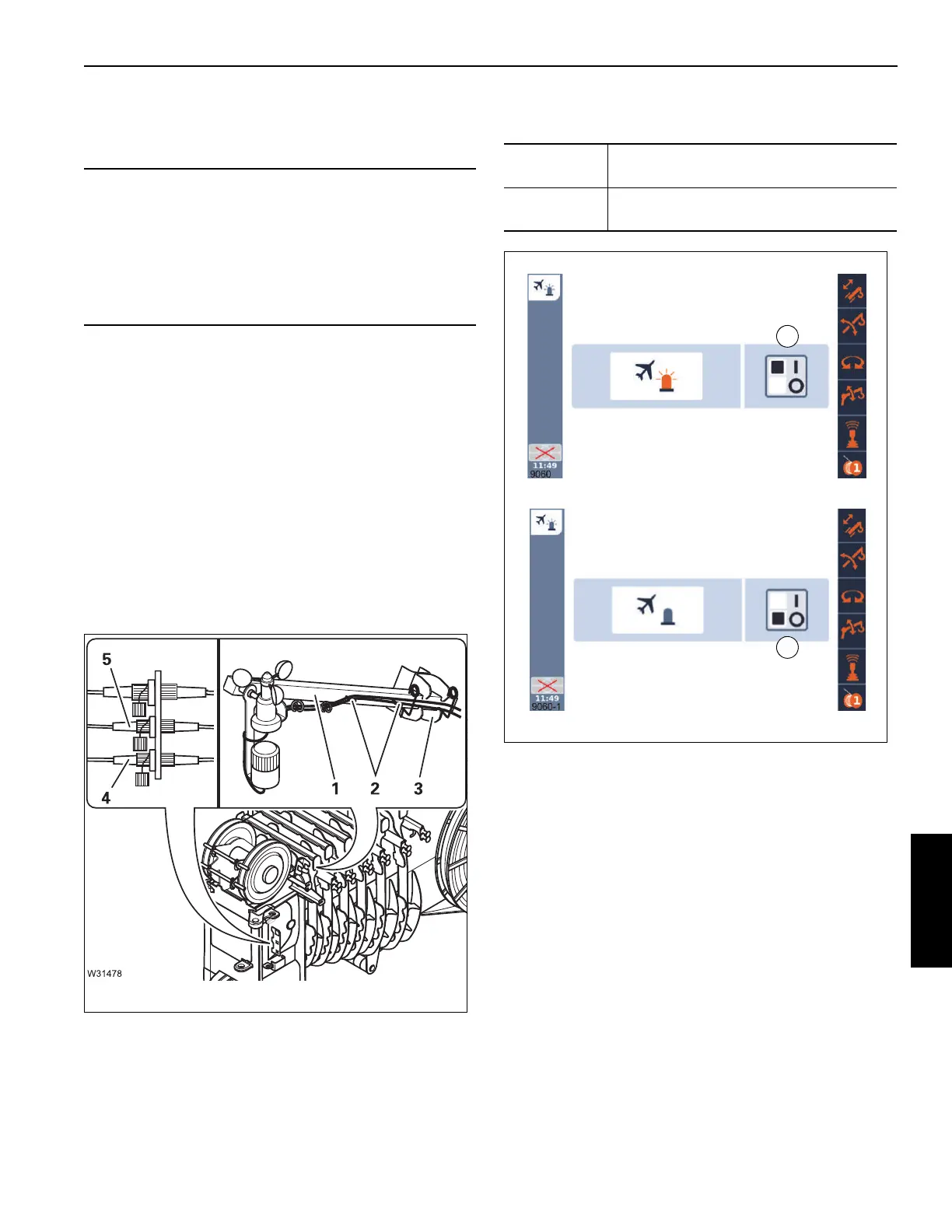
The anemometer and the boom position indicator light – if
provided – are located on the same rod.
• Insert the rod (1, Figure 5-86) into the holder (3) and
secure it with the retaining pins
• Remove the cable from the holders (2) and connect
- the anemometer to socket (4),
- the boom position indicator light to the socket (5).
• Lay the cables in such a way that they will not be
damaged during crane operation.
• Check that the anemometer is able to swing so that it
hangs vertically even when the main boom is raised.
Switching the boom position indicator light on and
off
CAUTION
Machine Damage!
Always remove the anemometer and boom position
indicator light before on-road driving.
This prevents the specified overall height being exceeded
at on-road level, and the anemometer from getting
damaged by being rotated too fast.
To switch on:
Select symbol (1, Figure 5-87) and
confirm – symbol ON is displayed
To switch off:
Select symbol (2) and confirm – symbol
OFF is displayed
 Loading...


