Grove Published 3-22-2021, Control # 702-02 5-53
GRT8120 OPERATOR MANUAL SET-UP AND INSTALLATION
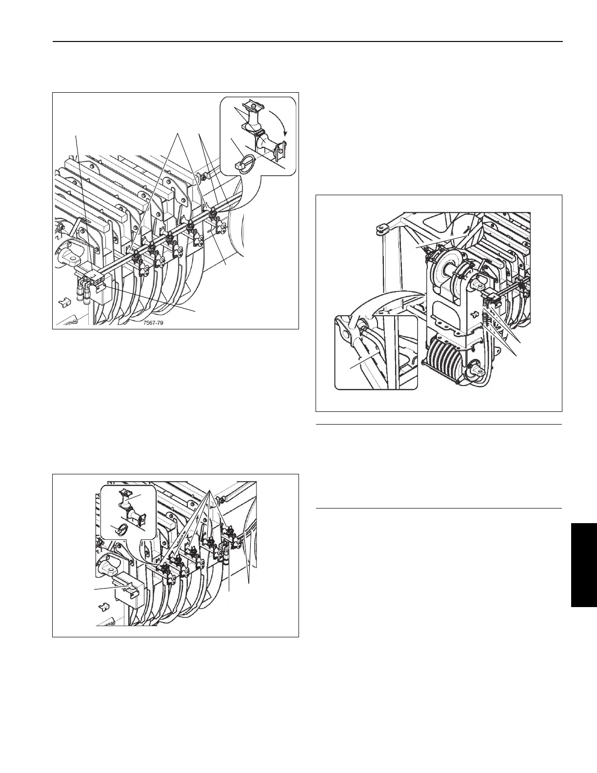
5. Fold down the guide sheaves (2) and secure them with
the hinged pins (1).
Retracting Hydraulic Hoses for Main Boom Operation
The locking device on the hose drum must be undone:
1. Loosen the hinged pins (5, Figure 5-75) and fold up the
guide sheaves (4).
2. Detach the strain relief from the holder (3) and attach it
to the holder (2).
3. Fold down the guide sheaves (4) and secure them with
the hinged pins (5).
Establishing the Hydraulic Connection
1. If necessary, bring the connections (1, Figure 5-76) into
the position for boom extension operations.
2. Remove the hose line (2) from the clamp (4).
3. Feed the hose lines towards the left hand side through
the lower opening (3) in the boom extension base
section under the boom head.
4. Remove the protective caps to the connections (1) and
attach the hose lines (observe color code).
FIGURE 5-75
7567-36
1
2
5
3
4
4
CAUTION!
Machine Damage!
Feed the hydraulic hoses under the main boom head in
such a way that they hang freely. Take care that the hoses
are not torn off when folding the boom extension base
section. This prevents damage to the hydraulic hoses.

 Loading...


