Grove Published 3-22-2021, Control # 702-02 5-39
GRT8120 OPERATOR MANUAL SET-UP AND INSTALLATION
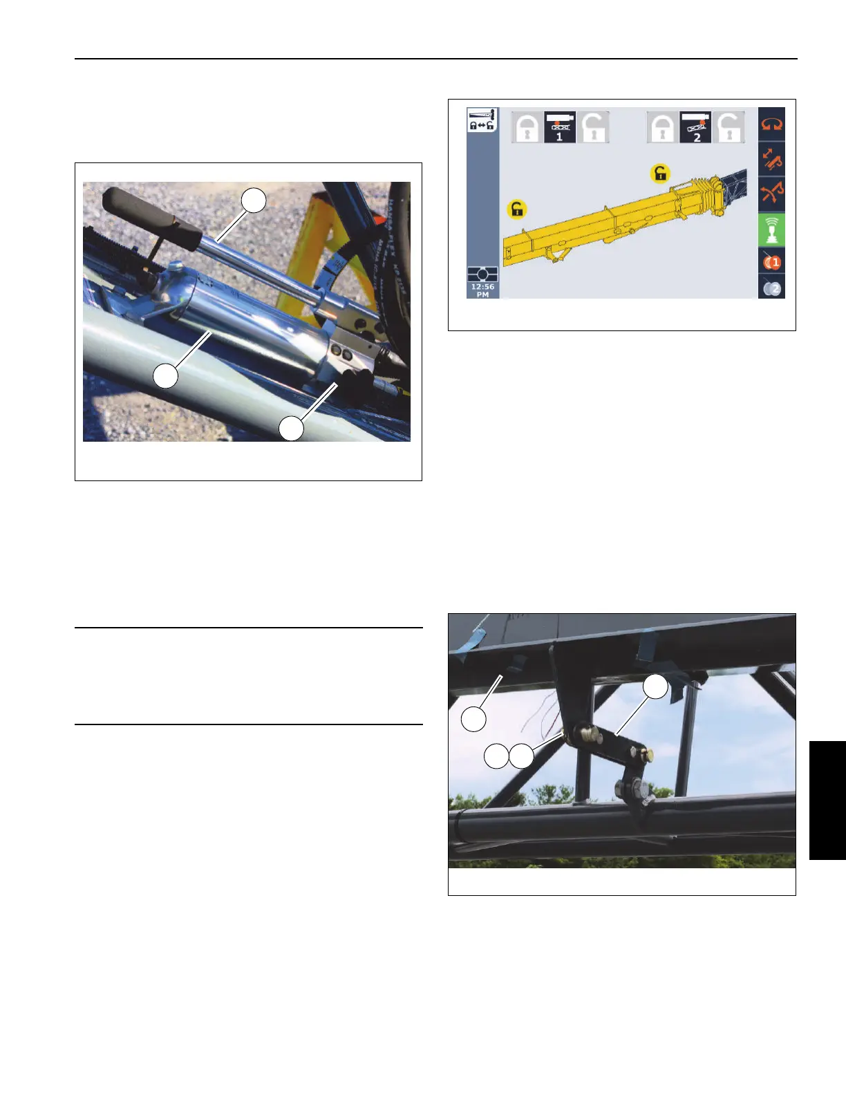
20. Install four pins (5, Figure 5-39) and retaining clips (6) to
secure the boom extension to the boom nose. If
necessary, use the jack (1, Figure 5-53) to install the
fourth pin:
a. Install three pins to attach the boom extension to the
boom nose.
b. Operate the jack handle (2) to align the holes on the
boom extension with the hole in the boom nose.
c. Install the fourth pin.
d. Secure all pins with retaining clips.
e. Turn the nob (3) to relieve the pressure to retract the
jack pin.
21. In the ODM display (Figure 5-54), make sure that ODM
shows that the boom extension is erected.
22. Remove the tag line.
23. Raise the mast sheave assembly. For more information,
see Folding Mast Sheave, page 5-59.
24. Erect the boom extension fly section following the
procedures under Erecting the Fly Section, page 5-39
Erecting the Fly Section
Use this procedure to erect the boom extension fly section.
NOTE: This procedure assumes the boom extension is
erected and fly extension is folded on the boom
extension base section.
1. Make sure the connecting link (1, Figure 5-55) is in
place that connects the fly section to the boom extension
base section together.
2. Make sure the attachment pin (1, Figure 5-56) and
retaining clip are in place that connects the ends of the
CAUTION
After installing the fourth pin, turn the pressure relief nob
(3) to retract the jack so the jack does not contact the
boom nose. Failure to retract the jack could result in
damage to the boom extension jack.
FIGURE 5-55
10088-11a
1
2 3
4

 Loading...


