5-38 Published 3-22-2021, Control # 702-02
SET-UP AND INSTALLATION GRT8120 OPERATOR MANUAL
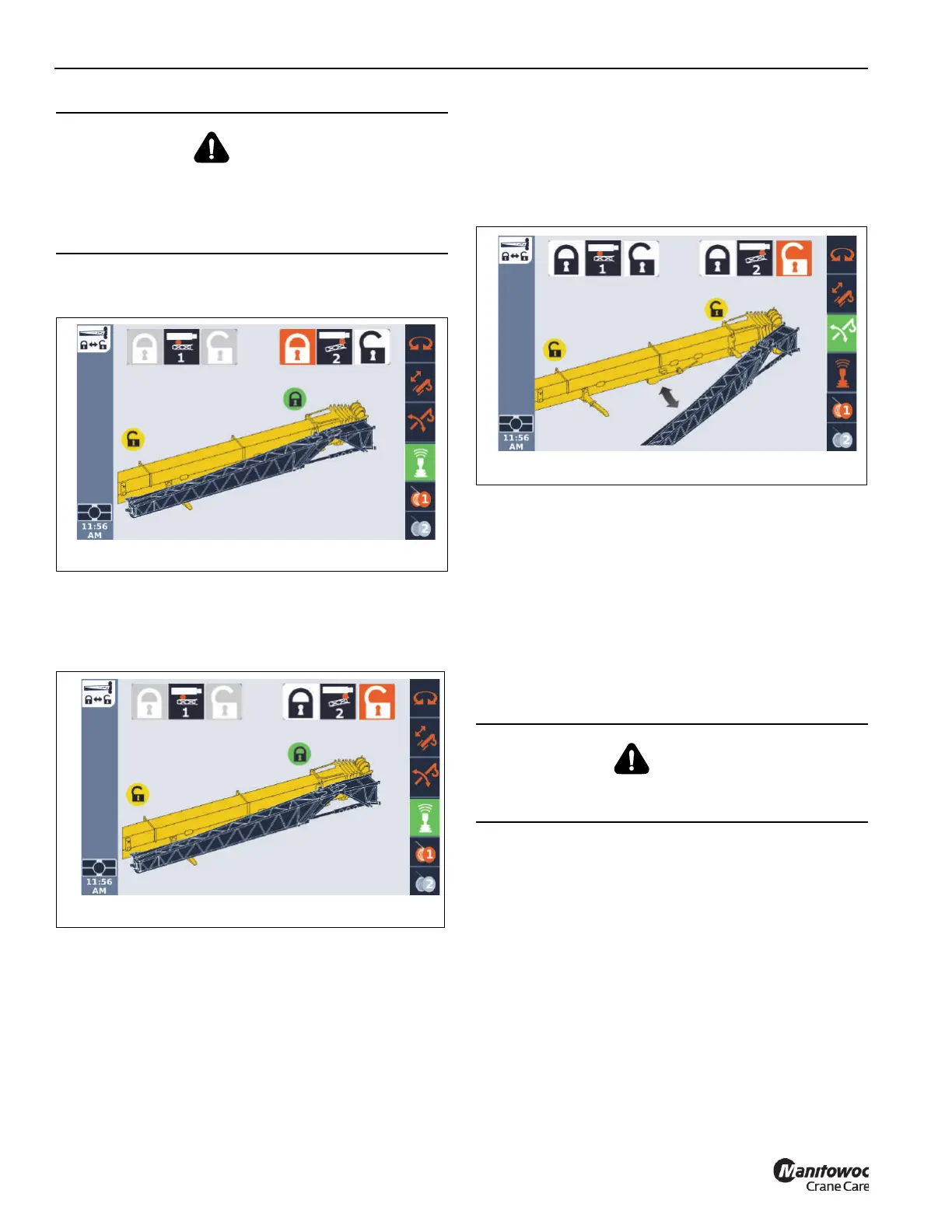
17. In the ODM (Figure 5-50), retract the front mounting pin
(Pin #2) as follows:
a. Use the ODM control pad arrow buttons or jog dial
to highlight unlock icon.
The unlock icon is highlighted (orange)
(Figure 5-51).
b. Press and hold the OK on the ODM control pad or
press down on the jog dial.
The lock status icon turns yellow, indicating the pin
is retracted. The boom extension is displayed as
detached from the side of the main boom
(Figure 5-52).
18. Visually confirm that the front mounting pin is unlocked.
The handle should be in the down position. When the
handle is in the down position, the front mounting pin is
retracted and the boom installation pins are locked.
NOTE: The front mounting pin (Pin #2) will not unlock
unless the right side boom extension installation
pins are fully engaged. If the front boom extension
pin (Pin #2) does not unlock, make sure the right
side boom extension installation pins are fully
engaged and the interlock pins are inserted
through the pins.
19. Slightly raise and/or lower the boom to help control the
boom extension. Using the tag line, swing the boom
extension to the front of the boom nose. Align the boom
extension anchor fittings with the main boom attachment
fittings.
DANGER
Crush Hazard
To avoid death or serious injury, ensure boom extension
installation pins (4, Figure 5-39) are installed prior to
retracting the front mounting pin (Pin #2).
DANGER
When erecting the boom extension, make sure that all
personnel and equipment are kept clear of the swing path.

 Loading...


