Grove Published 3-22-2021, Control # 702-02 5-37
GRT8120 OPERATOR MANUAL SET-UP AND INSTALLATION
12. Detach fly section from main boom base by doing the
following:
a. Remove retaining clip (1, Figure 5-46) from pin (2)
at fly section stowage bracket (3).
b. Pull pin (2) downward and turn counterclockwise to
lock in place.
c. Reinstall the retaining clip into the pin.
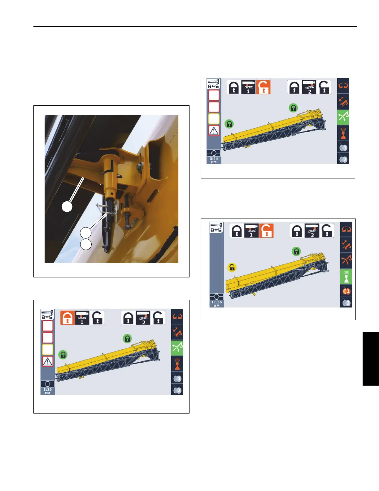
13. In the ODM (Figure 5-47), highlight the unlock icon and
retract the rear boom extension pin (Pin #1) as follows:
a. Use the ODM control pad arrow buttons or jog dial
to highlight the unlock icon.
The unlock icon is highlighted (orange)
(Figure 5-48).
b. Press and hold the OK on the ODM control pad or
press down on the jog dial.
The lock status icon turns yellow, indicating the pin
is retracted (Figure 5-49).
14. Visually confirm that the rear mounting pin is unlocked.
15. Using the tag line, swing the boom extension out on the
rear ramp so the boom extension installation pins
(4, Figure 5-39) align with the holes in the boom nose
attachment fittings.
16. With an impact wrench and 14 mm socket extension,
turn the jack screw (3, Figure 5-39) counterclockwise to
extend the boom extension installation pins (4) into the
boom nose attachment fittings. Extend jack screw until
the bolts and washers are at the end of the slots. Verify
that the pins (4) are fully engaged.
To be provided
10035-3
FIGURE 5-47

 Loading...


