5-36 Published 3-22-2021, Control # 702-02
SET-UP AND INSTALLATION GRT8120 OPERATOR MANUAL
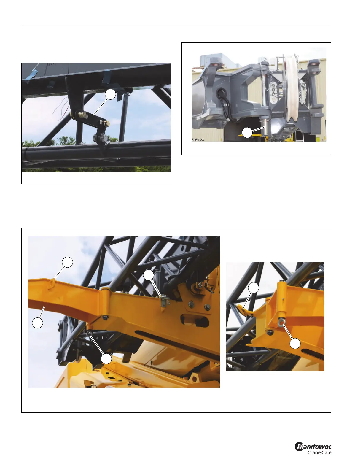
8. Make sure the connecting link (1, Figure 5-43) is in
place that connects the fly section to the boom extension
base section.
9. Make sure the attachment pin (1, Figure 5-44) and
retaining clip are in place that connects the ends of the
fly section and the boom extension base section
together.
10. Tie a tag line to the end of the boom extension base
section. The tag line will assist when swinging the boom
extension to the boom nose.
11. Retract the retaining pin (1, Figure 5-45) from the
bracket (2) to release the rear boom extension ramp (3)
from the stowed position. Fully swing the rear boom
extension ramp (3) into the erected position. Make sure
the pin (4) locks into position on the rear boom extension
bracket (5).
FIGURE 5-45
Deployed
10088-8a
1
2
3
4
Stowed
4
5
10088-9a

 Loading...


